Controlled Products Systems Group 1834-080 User Manual
Page 30
3.1.2
Programming from the Keypad
Follow the programming instructions as described in each section of this manual. The system will
prompt you with short tones (beep) when programming steps have been followed correctly, and with
a long tone (beeeeeep) when the programming step is ended. The display will also assist you in
viewing the information that you are programming. It is highly recommended that you complete the
resident listing in the appendix prior to starting any programming from the keypad. This listing will
provide you with the information needed to complete the manual programming sequence.
This symbol _ in the programming steps indicates numbers that you will need to enter; one number
per symbol. When programming from the keypad, after each programming step is performed
correctly, a short tone (beep) will be heard. When the programming session is ended, a long tone
(beeeeeep) will be heard.
NOTE: Relay hold open time zones, security levels, holiday schedules, anti-pass back IN / OUT
tables, anti-pass back re-sync schedules and elevator control functions cannot be
programmed from the system keypad. These functions can only be programmed from a PC
using the Remote Account Manager Software.
3.1.3
System Memory Identification
Beginning in January, 2010, all DKS 1830 series telephone entry systems come standard with 3000
memory (APB) chips installed in the system. The information below is to assist you with
programming older systems or when there is a need to change the memory chips to match a chip set
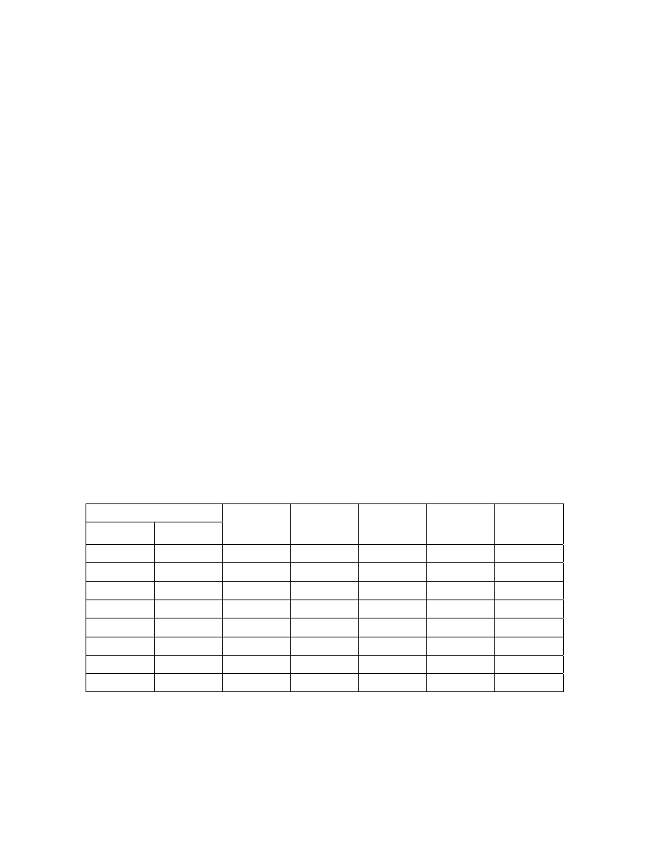
on another system already installed. Prior to starting the programming of the PC programmable
telephone entry system, you must know the memory capacity and type of the EEPROM chips that are
installed in the unit. This can be determined by inspecting the small chip that has a tag listing the
memory size on it and will be labeled APB if anti-pass back is enabled. The memory size determines
the number of residents, vendors, four-digit entry codes and device codes that can be stored in the
system. APB indicates that the chip set has anti-pass back capability. The table shows the valid
numbers available with each memory level.
Part Number
Standard
System
Memory
Phone
Number
Capacity
Name
Capacity
Entry Code
Capacity
Device
Code
Capacity
APB
1835-150
1835-140
25 25 25 25 625
1835-151
1835-141
75 75 75 75
1875
1835-152
1835-142
125 125 125 125 3125
1835-153
1835-143
250 250 250 250 6250
1835-154
1835-144
500 500 500 500 8000
1835-155
1835-145
1000 1000 1000 1000 8000
1835-156
1835-146
2000 2000 2000 2000 8000
1835-157
1835-147
3000 3000 3000 3000 8000
Page
30
1835-065-R-10-11