2 controller & expansion boards 1-8 – Controlled Products Systems Group 1834-080 User Manual
Page 25
2.3.2
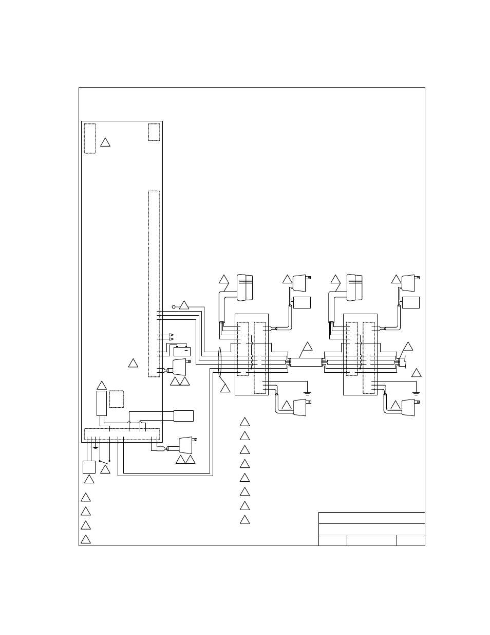
Controller & Expansion Boards 1-8
C.O.
PHN
Elevator
Control
RS 232
Connection
A
u
xili
a
ry Ter
m
in
als
Mai
n
T
e
rmi
n
al
Relay 0
4
5
18
33,
1
83
5, 1
8
37
, 18
3
8
CON
T
ROLLE
R
Board 1
System Relay 3
GRN
WHT
BLK
RED
P2
P1
6
7
8
9
10
17
5
6
7
8
9
12
13
14
6
6
6
9
7
7
4
4
10
10
30 Series Controller to 2351-010 Expansion Boards 1-8
Detail Wiring
2351-010
Board 2
System Relay 4
To
Boards
3-8
N
O
TE
S:
Co
nt
ro
lle
r
ma
in
te
rm
in
a
ls
15-
1
6
-1
7 =
SY
S
T
E
M
R
E
LA
Y
1.
Co
nt
ro
lle
r
ma
in
te
rm
in
a
ls
13-
1
4
= SY
STEM
RE
LAY 2.
6 conductor, stranded with overall shield, 18, 20, 22 or 24 gauge is
sufficient for these connections.
4 conductor, stranded with overall shield, 18, 20, 22 or 24 gauge is
sufficient for these connections.
Communication cable to additional boards is connected in parallel.
Allows “teeing” of communication cable for optimal cable routing.
16 Volt, 20 VA UL Listed Transformer.
For 1837, use 16 Volt, 40 VA UL Listed Transformer.
Power for door strikes or magnetic locks is not provided by the
system. It must be provided by an external power supply.
Aux power transformer must be connected. Otherwise, RS232,
elevator control and weigand inputs will not function.
No connection at controller.
12
9
10
11
5
6
7
8
1
2
3
4
5
6
1
2
3
1 2 3
17
16
15
14
13
20
19
NO
NC
COM
14
13
12
11
10
9
8
7
6
5
4
3
2
1
11
4
16 VAC
OUTPUT
8
Battery Backup - separate batteries required for phone
system and weigand terminals.
3
4
6
18
-
12 VD
C
I
N
PU
T
+
12 VD
C
I
N
PU
T
MAIN
DR/GATE
1
1
Central Office phone line - touch tone, loop start.
2
2
A switch closure across terminals 4 & 6 will activate relay 1
for its programmed strike time.
3
3
4
12
See Dwg No. M1835-065-5
for detail.
DOORKING, INC., INGLEWOOD, CA 90301
Date:
Dwg. No.
Detail Wiring - 30 Series Controller to 2351-010
Expansion Boards 1-8
Rev.
Title:
10/11
D
M1835-065-3
16 VAC
PWR
INPUT
16 VAC
PWR
INPUT
16 VAC
PWR
INPUT
NEG 12 VDC INPUT
POS 12 VDC INPUT
+ 12 VDC
COMMON
DATA 1
DATA 0
16 VAC
PWR
INPUT
LOCK
PWR
DOOR
LOCK
LOCK
PWR
DOOR
LOCK
GRN
WHT
BLK
RED
RED
BLK
WHT
GRN
BRN
BLU
RED
BLK
WHT
GRN
BRN
BLU
+
P2
P1
6
7
8
9
10
17
5
6
7
8
9
12
13
14
2351-010
RED
BLK
WHT
GRN
BRN
BLU
RED
BLK
WHT
GRN
BRN
BLU
1835-065-R-10-11
Page
25