Controlled Products Systems Group SMDRG User Manual
Page 2
IN
S
T
R
,I
N
S
T
,S
M
D
R
G
L
in
e
a
r
P
/N
:
2
1
7
7
5
0
A
M
a
te
ri
a
l:
2
0
L
b
.
M
e
a
d
B
o
n
d
S
iz
e
:
8
.5
0
0
"
x
1
1
.0
0
0
"
In
k
:
B
la
c
k
S
c
a
le
:
1
-1
S
id
e
2
o
f
2
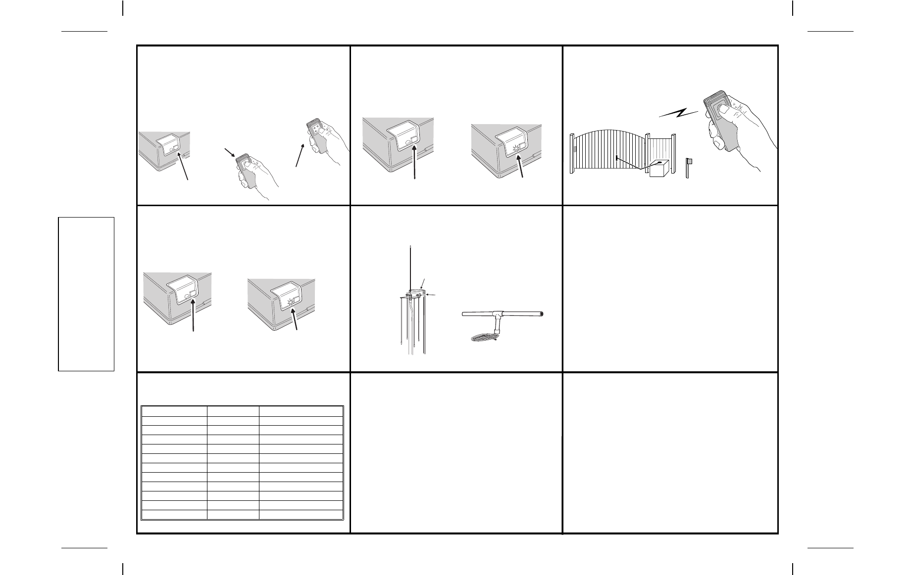
STEP 6
Add additional transmitters. Repeat Step 5 for each
transmitter used with this receiver. Be sure to press the receiver’s
program button
each time a new transmitter or a different
transmitter button on a multi-button transmitter is pressed.
If the LED doesn’t come on when the receiver’s program button
is pressed, the receiver’s memory is full (40 transmitters total).
Use the erase function (Info 1) to remove ALL previously learned
transmitters from the receiver’s memory.
STEP 7
Review memory. Press and hold the receiver’s
program button until the LED begins to flash (about 3 seconds)
and then release the button. Count the number of flashes. The
number of flashes equals the number of transmitters programmed
into the receiver.
➥ NOTE: Don’t hold down the programming button longer
than 5 seconds, the receiver’s memory for that channel will
be erased (Info 1).
STEP 8
Test receiver.
Be sure gate area is clear. Activate
each transmitter. The receiver relay should click and the operator
should activate. Wait 1 second between each activation.
INFO 1
Erasing receiver memory. Transmitters may be
erased from the receiver’s memory by pressing and holding the
receiver’s program button for 5 seconds or more. After the LED
blinks (count of transmitters) it will blink one more time as the
receiver’s memory is erased. All transmitters are erased at the
same time.
INFO 2
Mounting the Remote Antenna. Attach antenna to
post as shown or refer to antenna instructions for other options.
➥ NOTE: If the receivers LED flashes continuously when a
transmitter isn’t being activated, the receiver is too close to an
electrical noise source. Move the receiver away from the noise
source or call technical services for assistance.
TRANSMITTER COMPATABILITY TABLE
The Model SMDRG receiver can be used with any of the following
transmitter models.
PART NUMBER
MODEL NUMBER
DESCRIPTION
ACP00605
ACT-21B
SINGLE CHANNEL
ACP00616
ACT-22B
TWO CHANNEL
ACP00728/877
MT-1/MT-1B
SINGLE CHANNEL
ACP00729/746
MT-2/MT-2B
TWO CHANNEL
ACP00879
ACT-31B
SINGLE CHANNEL
ACP00872
ACT-34B
FOUR CHANNEL
DNT00052A
MDT-1/MDT-1B
SINGLE CHANNEL
DNT00053A
MDT-2/MDT-2B
TWO CHANNEL
DNT00054A
MDT-4/MDT-4B
FOUR CHANNEL
DNT00058/ACP00878
MDTK/MDKP
KEYPAD TRANSMITTER
DNT00053B/ACP00720B
MDT-2B/MDT-2BB
TWO CHANNEL
LIMITED WARRANTY
This product is warranted to the consumer against defects in material
and workmanship for one year from the date of purchase. This
warranty applies to first retail buyers of new devices. Warrantor will
repair, or at its option, replace, any device it finds that requires service
under this warranty, and will return the repaired or replaced device to
the consumer at the warrantor’s cost. For warranty service and
shipping instructions contact warrantor at the address shown below.
Devices must be sent to warrantor for service at owner’s expense.
The remedies provided by this warranty are exclusive. Implied
warranties under state law are to the one year period of this written
warranty. Some states do not allow limitations on how long an implied
warranty lasts, so the above limitation may not apply to you. In order
to be protected by this warranty, save your proof of purchase and send
copy with equipment should repair be required. This warranty gives
you specific legal rights, and you may also have other rights which
vary from state to state.
All products returned for warranty service require a Return Product
Authorization Number (RPA#). Contact Linear Technical Services
at 1-800-421-1587 for an RPA# and other important details.
IMPORTANT !!!
Linear radio controls provide a reliable communications link and fill
an important need in portable wireless signaling. However, there are
some limitations which must be observed.
✶
For U.S. installations only: The radios are required to comply with FCC
Rules and Regulations as Part 15 devices. As such, they have limited
transmitter power and therefore limited range.
✶
A receiver cannot respond to more than one transmitted signal at a time
and may be blocked by radio signals that occur on or near their operating
frequencies, regardless of code settings.
✶
Changes or modifications to the device may void FCC compliance.
✶
Infrequently used radio links should be tested regularly to protect against
undetected interference or fault.
✶
A general knowledge of radio and its vagaries should be gained prior to
acting as a wholesale distributor or dealer, and these facts should be
communicated to the ultimate users.
Copyright © 2000 Linear Corporation
217750 A
P R E S S P R O G R A M B U T T O N F I R S T
T H E N P R E S S T R A N S M I T T E R B U T T O N
W I T H M U L T I - B U T T O N
T R A N S M I T T E R S P R E S S
T H E D E S I R E D B U T T O N
PRESS TRANSMITTER
BUTTON TO TEST
WARNING!
BE SURE GATE
AREA IS CLEAR
OF OBSTRUCTIONS
PRESS PROGRAM BUTTON
FOR FIVE SECONDS OR MORE
LED WILL FLASH, COUNTING THE
TOTAL NUMBER OF TRANSMITTERS
PROGRAMED. THEN IT WILL BLINK
ONE OR MORE TIME AS THE TRANSMITTERS
ARE ERASED
PRESS PROGRAM BUTTON
FOR THREE SECONDS
THEN RELEASE
LED WILL FLASH, COUNTING THE
TOTAL NUMBER OF TRANSMITTERS
PROGRAMED
U-BOLT
2" MAXIMUM
DIAMETER
EXA-1000
ANTENNA
EXA-2000
DIRECTIONAL
ANTENNA