Controlled Products Systems Group SMDRG User Manual
Smdrg, Digital gate receiver, Installation instructions
IN
S
T
R
,I
N
S
T
,S
M
D
R
G
L
in
e
a
r
P
/N
:
2
1
7
7
5
0
A
M
a
te
ri
a
l:
2
0
L
b
.
M
e
a
d
B
o
n
d
S
iz
e
:
8
.5
0
0
"
x
1
1
.0
0
0
"
In
k
:
B
la
c
k
S
c
a
le
:
1
-1
S
id
e
1
o
f
2
MegaCode Series
SMDRG
DIGITAL GATE RECEIVER
Installation Instructions
(800) 421-1587
• www.linearcorp.com
DESCRIPTION
The MegaCode series of digital receivers are wireless radio controls
designed for use with automatic gate openers or garage door
operators. The MegaCode radio format provides unparalleled security.
The transmitter and receiver can be programmed to more than a million
different codes.
MegaCode receivers and transmitters do not contain a typical “coding
switch”. Each transmitter is pre-set at the factory to a unique code. The
receiver is programmed by sending a signal to it from the transmitter(s)
that are going to be used with it. This stores the transmitters code into
the receiver’s memory. The receiver will retain its memory even without
power. The receiver will activate only from these “memorized”
transmitters. Each MegaCode receiver can remember a maximum
of 40 transmitters.
Receivers are normally powered with 24 volts AC/DC from the gate
operator. The SMDRG has a built-in type “F” connector and is supplied
with a 9 inch local antenna. The Linear EXA-GP or EXA-2000 Remote
Antenna may be used to enhance the operational range of the SMDRG.
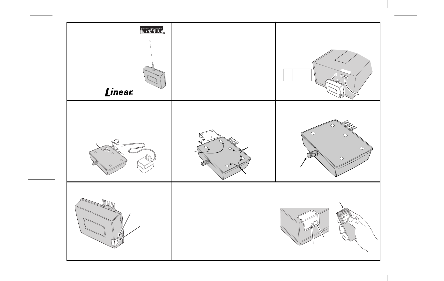
STEP 1A
SMDRG Three-terminal Operator Installation.
Hold receiver up to back of operator. (Refer to the gate operator
or garage door operator manual for specific wiring instructions.)
Connect Terminals 1, 2 & 3 on the receiver to Terminals 1, 2 & 3
on the operator. Operator power supply output must be 24V.
STEP 1B
SMDRG Installation (For non 24V Operator). A
Model TF524 step-down transformer must be used to power the
receiver when connecting to an operator supplying anything other
than 24V. Install the screws supplied into the brass terminals on
the receiver. Connect the transformer wires to Terminals 1 & 3
(polarity not important). Connect receiver Terminals 1 & 2 to the
two operator activation terminals (polarity not important).
STEP 2
Optional Receiver Mounting Bracket. If the receiver
isn’t going to be mounted directly to the operator terminals, an
optional mounting bracket is supplied. It can be installed three
ways onto the SMDRG case. Screw the bracket to a wall or stud
and snap the receiver onto it.
STEP 3
Installing the antenna. Attach the local antenna by
screwing it onto the “F” connector.
STEP 4
SMDRG Program button and LED Location. Locate
the program button and LED on the side of the receiver case.
STEP 5
Program receiver. Momentarily press the receiver’s
program button. The red programming LED will light if there’s
room in the receiver’s memory for another transmitter (40
maximum per receiver). The LED stays on for about 5 seconds.
A transmitter must be entered
while the LED is on. Press the
desired transmitter button. The LED will flicker indicating that the
receiver has accepted the transmitter.
➥ NOTE: Be sure to press the receiver program button for less
than 2 seconds.
➥ WARNING! Operator will not activate when the receiver is
being programmed from the transmitter, but the gate
operator will activate the next time the transmitter is
activated after programming.
➥ NOTE: The programming LED also monitors radio signals
entering the receiver. It is common to see an occasional blink
from the LED. The LED will also light when any transmitter
tuned to the receiver’s frequency (programmed into the
receiver or not) is activated.
1
2
3
1
2
3
CONNECT
RECEIVER
DIRECTLY
TO OPERATOR
MATCH UP
TERMINAL
NUMBERS
!
COMMON
GROUND
RELAY
24-VOLTS
RADIO
POWER
1
2
3
INSTALL 3 SCREWS
WIRE TRANSFORMER TO TERMINALS 1 & 3
USE MODEL
#TF524 24VAC, .5VA
TRANSFORMER
WIRE TERMINALS 1 & 2 TO OPERATOR
PUSHBUTON TERMINALS
B RA CK E T CA N
MO UNT IN THRE E
P L A C E S
LO CA TIO N 1
LO CA TIO N 2
LO CA TIO N 3
CO RNER HOLE I S
S HA RE D F O R
LOCATIONS 2 & 3
1
2
3
1
2
3
"F" CONNECTOR
PRESS AND RELEASE PROGRAM
BUTTON
PROGRAMMING
BUTTON
LED WILL LIGHT
WHEN RECEIVER
IS READY
WHEN RECEIVER
IS READY, PRESS THE DESIRED
TRANSMITTER BUTTON
RECEIVER LED
WILL FLICKER
AS TRANSMITTER
IS ENTERED INTO
MEMORY
PROGRAMMING
BUTTON
PROGRAMMING
LED