Limited warranty – Controlled Products Systems Group MGT User Manual
Page 2
INS
T
R,INS
T
,MGT (MA
NUA
L)
Linear P
/N: 210025 B
Material: 20 Lb. Mead B
ond
S
ize: 8 .500" x 11.000"
Ink: B
lack
S
c
ale: 1-1
S
ide 2 of 2
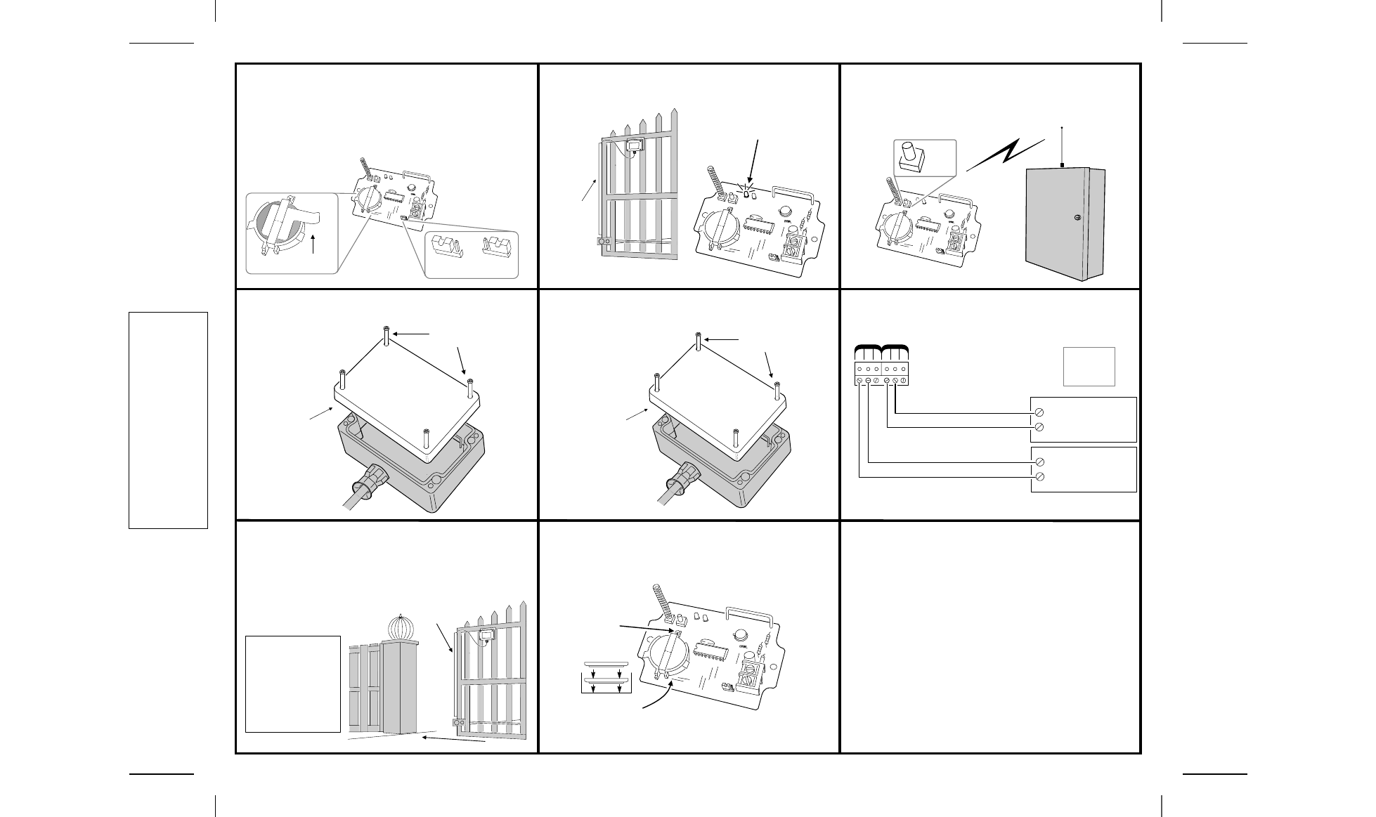
STEP 7
Set Jumper. Remove the battery protection strip. The
MGT monitors the edge sensor for short circuits and cut wiring by
measuring the edge sensor capacitance value. This function works
with edge sensors such as Miller Edge Models MGR20 and MGS20.
Some edge sensors may not present enough capacitance to pass
this test. If a constant loop trouble condition is being indicated the
test can be disabled by setting the Open Loop Test Option Jumper
to the OFF position.
STEP 8
Test Safety Edge. Test safety edge connection by
pressing the safety edge. The power light should come on.
STEP 9
Program Transmitter. Refer to receiver programming
instructions to set the receiver into the program mode. Press the “test”
button to program the unit identification code into the receiver.
Facility/ID code is located on the inside of the unit, near the terminal
block.
STEP 10
Reset Trouble Indicator. Close transmitter cover and
reset any trouble indicators on receiver caused by the open cover.
STEP 11
Test Tamper. Open transmitter cover and check receiver
to see that a tamper is indicated. Replace cover when finished.
STEP 12
Wire Receiver. Wire receiver obstacle output to obstacle
input on operator. Refer to operator and receiver wiring instructions.
TEST
BUTTON
REPLACE
COVER
TIGHTEN
SCREWS
LOOSEN
SCREWS
REMOVE
COVER
STEP 13
Test System. Activate the gate to close. As the gate is
closing, press the safety edge with your hand. Gate should stop and
reverse
☞
CAUTION! DO not stand in the path of the closing gate.
STEP 14
Replacing Batteries. Remove the screw on the battery
clip to remove batteries. Place two Duracell Lithium 3V type DL 2450
batteries with the (+) side up in the battery compartment and replace
clip and screw.
LIMITED WARRANTY
This Linear product is warranted against defects in material and workmanship for twelve (12) months. The
Warranty Expiration Date is labeled on the product. This warranty extends only to wholesale customers who
buy direct from Linear or through Linear’s normal distribution channels. Linear does not warrant this product to
consumers. Consumers should inquire from their selling dealer as to the nature of the dealer’s warranty, if any.
There are no obligations or liabilities on the part of Linear Corporation for consequential damages arising
out of or in connection with use or performance of this product or other indirect damages with respect to
loss of property, revenue, or profit, or cost of removal, installation, or reinstallation. All implied warranties,
including implied warranties for merchantability and implied warranties for fitness, are valid only until Warranty
Expiration Date as labeled on the product. This Linear Corporation Warranty is in lieu of all other warranties
express or implied.
All products returned for warranty service require a Return Product Authorization Number (RPA#). Contact Linear
Technical Services at 1-800-421-1587 for an RPA# and other important details.
Important!!!
Linear radio controls provide a reliable communications link and fill an important need in portable wireless signaling.
However, there are some limitations which must be observed.
1
For U.S. installations only: The radios are required to comply with FCC Rules and Regulations as Part 15
devices. As such, they have limited transmitter power and therefore limited range.
1
A receiver cannot respond to more than one transmitted signal at a time and may be blocked by radio signals
that occur on or near their operating frequencies, regardless of code settings.
1
Changes or modifications to the device may void FCC compliance.
1
Infrequently used radio links should be tested regularly to protect against undetected interference or fault.
1
A general knowledge of radio and its vagaries should be gained prior to acting as a wholesale distributor or
dealer, and these facts should be communicated to the ultimate users.
Copyright
2002 Linear Corporation
210025 B
POWER INDICATOR SHOULD
LIGHT WHEN SAFETY EDGE
IS PRESSED
PRESS
WITH
HAND
TEST ON
TEST OFF
REMOVE BATTERY
PROTECTION STRIP
OPEN LOOP
N.O. COM. N.C. N.O. COM. N.C.
CHANNEL C
CHANNEL D
NOTE:
ONE OR TWO
OPERATORS
MAY BE USED
EXIT
GATE
OPERATOR
ENTRY
GATE
OPERATOR
NORMALLY OPEN
OBSTACLE
INPUT
NORMALLY OPEN
OBSTACLE
INPUT
NO
T
USED
NO
T
USE
D
Typical
AccessMaster Hook-up
WARNING!
NO AUTOMATIC
SUPERVISION OF
A DAMAGED GATE
EDGE SENSOR IS
PROVIDED. USER IS
CAUTIONED TO TEST
THE TRANSMITTER
REGULARLY.
PRESS
SAFETY EDGE
CLOSE GATE
REMOVE
SCREW
+
-
+
-
INSTALL TWO
DURACELL
TYPE DL2450
BATTERIES (+)
SIDE UP