Controlled Products Systems Group MGT User Manual
Controlled Products Systems Group Hardware
INS
T
R,INS
T
,MGT (MA
NUA
L)
Linear P
/N: 210025 B
Material: 20 Lb. Mead B
ond
S
ize: 8.500
" x 11.000"
Ink: B
lack
S
c
ale: 1-1
S
ide 1 of 2
MGT
GATE SAFETY EDGE
TRANSMITTER
Installation
Instructions
DESCRIPTION
The MGT is part of Linear’s Access Control product line and is the only fully
supervised gate edge safety transmitter on the market today. In a typical installation,
the MGT is mounted on a motorized gate, door or barrier arm and wired to a standard
exterior safety edge sensor which presents a closed circuit across the connecting
wires when an object is hit during the closing of a gate. To insure full compatibility
with all gate edge supervision features, Linear recommends Miller gate edge
sensors with an optional capacitor (.001 UF) installed. Please specify when ordering
sensor. If the edge sensor is pressed for 1/8 second, the MGT transmits a message
to the AccessMaster or AccessPro to reverse the movement of the gate. A status
message is sent to the receiver once every hour which indicates battery condition
and that the transmitter is operational. If the edge sensor becomes disconnected or
shorted, the status transmission informs the receiver that a trouble condition exists.
The MGT also features a tamper switch which will send a trouble transmission when
the cover is removed.
The MGT circuit board has been coated to prevent moisture damage and is mounted
inside a weather resistant fiberglass box. The mounting box attaches to the gate
through sealed interior mounting screws.
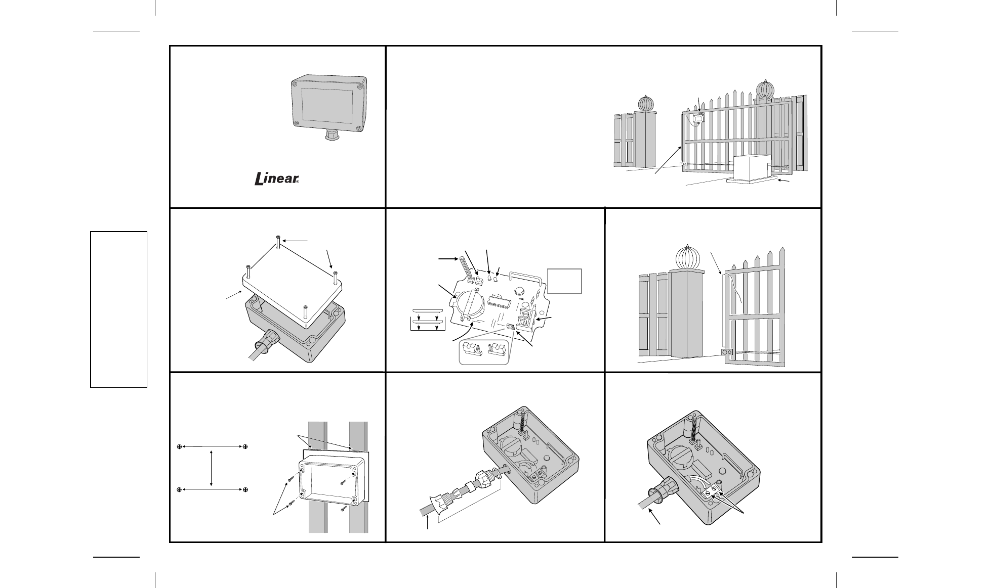
STEP 1
Remove Cover. Loosen the four screws on transmitter
top and remove cover.
STEP 2
Locate Parts. Refer to diagram below for transmitter
parts location and details.
STEP 3
Mount Safety Edge. Mount safety edge according to
manufacturer’s instructions included with the product.
STEP 4
Mount MGT. Choose a location as high as possible on
gate in a secure position. Use the template attached to mark the
location for the transmitter. You may have to attach a metal or wood
plate to mount transmitter. Use a 3/32" bit and drill holes. Attach MGT
to gate using the four #6 self-tapping drill point screws.
STEP 5
Assemble Cable Grip. Unscrew the cable grip about 3/4
of the way and thread the safety edge cable through the cable entry
on the transmitter.
STEP 6
Attach Cable. Attach safety edge cable to terminals as
shown. Tighten cable grip assembly using pliers to assure a water
tight seal.
DTG
TRANSMITTER
SAFETY EDGE
SENSOR
GATE
OPERATOR
LOOSEN
SCREWS
REMOVE
COVER
BATTERY
HOLDER
+
-
+
-
INSTALL TWO
DURACELL
TYPE DL2450
BATTERIES (+)
SIDE UP
TAMPER
SWITCH
TEST
BUTTON
POWER LIGHT, LIGHTS WHEN TRANSMITTING
(STEADY=NORMAL, FLASH=LOW BATTERY)
LOOP TROUBLE LIGHT
(ON WHEN SENSOR LOOP IS OPEN
OR SHORTED DURING TEST)
SAFETY
EDGE
INPUT
TERMINALS
LOOP TROUBLE TEST
OPTION JUMPER
NOTE:
LIGHTS ONLY
WORK WITH
COVER OFF
LOOP
TEST ON
LOOP
TEST OFF
ATTACH DTG
TO PLATE
3.88"
1.77"
WELD PLATE
TO GATE
INSTALL
SAFETY EDGE
CA
BL
E G
RI
P A
SS
EM
BL
Y
TO SAFETY EDGE
TYPICAL INSTALLATION
ATTACH EDGE
SENSOR CABLE
TO TERMINALS
TO SAFETY EDGE
(760) 438-7000 • FAX (760) 438-7043
USA & Canada (800) 421-1587 & (800) 392-0123
Toll Free FAX (800) 468-1340
www.linearcorp.com