Controlled Products Systems Group 318N User Manual
Page 4
2 - English
EN
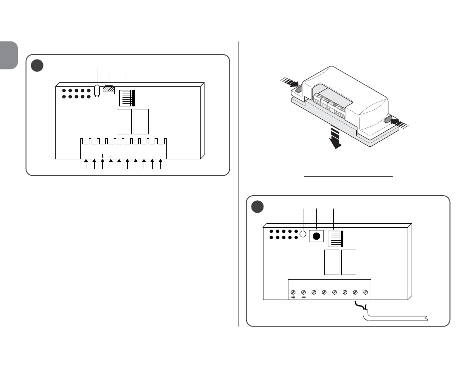
Fig. 1 illustrates the electrical connections on the connector:
A = not used
B = electricity supply
C = relay 1 output
D = relay 2 output
E = aerial
• For models with universal connection
These models with a terminal board make universal use pos-
sible; they can be wall-mounted using screws (not provided)
or using the adhesive on the bottom of the box.
––– Electrical connections –––
Make the connections as follows (fig. 2):
2
1 2 3 4 5 6 1 2
L1 P1 BM
1
1
2
AERIAL
Opening of the box for receivers with universal connection:
L1 P1
BM
A
B
C
D
E
1
relay 1
relay 2
relay 1
relay 2
See also other documents in the category Controlled Products Systems Group Hardware:
- CVT-OPTW (5 pages)
- CVX-1300 (28 pages)
- SPX-5621 (20 pages)
- SPX-5551 (20 pages)
- SPX-5601 (18 pages)
- SPX-7200 (22 pages)
- SPX-7400 (18 pages)
- SPX-7410 (18 pages)
- SPX-7500 (17 pages)
- WDG-5912 (37 pages)
- 030212 (3 pages)
- 108210 (2 pages)
- MC2022 (2 pages)
- 302850 (1 page)
- MVP-1CH-24V-4W-FC (2 pages)
- 298601 (2 pages)
- 300MC (1 page)
- 302210 (4 pages)
- 307010 (2 pages)
- 308301 (2 pages)
- 308302 (2 pages)
- 308913 (2 pages)
- 309013 (1 page)
- 355LM (2 pages)
- 414001 (2 pages)
- 420001 (2 pages)
- 466LM (1 page)
- 9921MT (2 pages)
- 9931T (2 pages)
- AM-RRR (2 pages)
- DD (1 page)
- DR-1 (1 page)
- DRA (1 page)
- DT (1 page)
- DT-4A (1 page)
- DTG (2 pages)
- DTKP (1 page)
- G3T-BX (2 pages)
- GITR-3 (2 pages)
- GK-BX (4 pages)
- GLR-BX (1 page)
- GM3T (1 page)
- GRD-2 (1 page)
- MCT-2 (1 page)