Controlled Products Systems Group SPX-7500 User Manual
Page 9
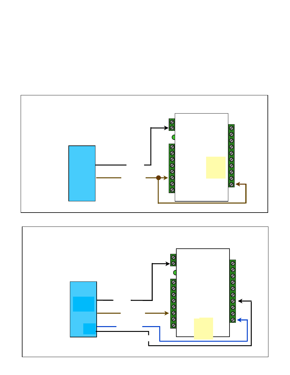
Cypress Suprex 7500 Series - Door Strike and LED I/O
Only Relay and LED Connections are shown for clarity, refer to previous diagrams for Power and Data connections.
To activate the relay on the Remote unit, connect as shown below. These connections can be used
to allow the Remote relay to operate a DOOR STRIKE, GATE, or other locking hardware. Refer to
following pages in this document for details of each I/O operation and connection.
There are two relays available for accessory outputs at the Remote end. Either relay can be used
to provide the Door Strike or Gate activation function. This example uses Relay 1.
Wiring Example - Door Strike does not follow LED
LED Signal
Strike Signal
Access
Control
Panel
N.O.
Com
Ground
Ground
Ground
Suprex Central
R1 Input
Controls
Strike on
Remote
Ground
R1 IN
LED In
Wiring Example - Door Strike Follows LED
Access
Control
Panel
LED In
R1 IN
R1 Input
Controls
Strike on
Remote
Suprex Central
Ground
LED Signal
Ground