Chapter 1: installation, Verview, Lanning – Controlled Products Systems Group SLIDESMART DC 10F User Manual
Page 23: Installation, Chapter 1 s
Site Overview & Planning
Revision D
Installation
1-1
Installation
Chapter 1
S
ITE
O
VERVIEW
& P
LANNING
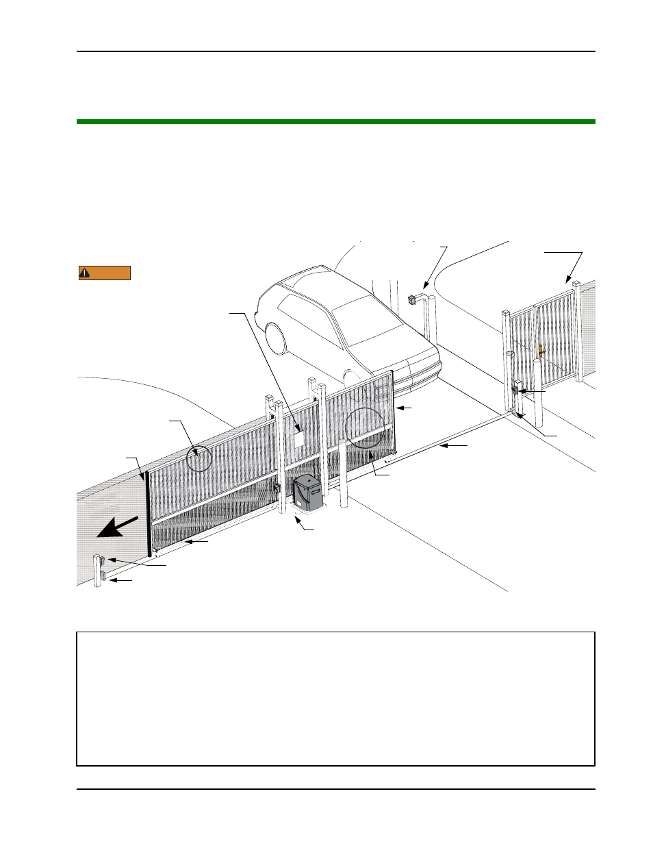
Figure 1-1.
SlideSmart DC 15
SlideSmart DC 10F
Duty cycle: continuous
Duty cycle: continuous
Power, single phase: Switch selectable
Power, single phase: Switch selectable
115 volts, 3 amps, 50/60 Hertz
115 volts, 3 amps, 50/60 Hertz
230 volts, 1.5 amps, 50/60 Hertz
230 volts, 1.5 amps, 50/60 Hertz
Motor:
½
hp
Motor:
½
hp
Gate speed: 1ft/s
Gate speed: 2ft/s
Gate weight: Maximum 1500lbs (675kg)
Gate weight: Maximum 1000lbs (450kg)
Note:For SlideSmart DC Solar operators, refer to www.hysecurity.com
Secure Side
Public Side
LeŌ Hand Ga
te
opening
nd Ga
te
g
Pedestrian gate
To comply with ASTM F2200, a screened wire mesh
Maximum 2
¼
” (57mm) width
between vertical bars
Target magnet on chain
Photo eye (entrapment protection shown in four locations)
Physical stop - weld stops at both ends of V track
Earth ground
Edge sensor
Edge sensor on
V track
Photo eye
Physical
stop
Make sure a separate walk-
through entrance is avail-
able and its pedestrian
path is clearly
designated.
Attach WARNING Signs
Be sure to place the
WARNING signs on both
sides of the gate. For your records, take a
photograph of the completed installaƟon site.
WARNING
Mount access control
beyond gate.
devices at least 6ft
Keypad or Card Reader
on trailing
edge
leading edge
extends to the top of the gate or to a minimum
height of 6 ft. (183cm) if a 2¼” (57mm) or larger
gap exists between the vertical bars.