Entrapment protection devices, Additional, Features – Controlled Products Systems Group RSL12V User Manual
Page 24
Inside
Pr
oper
ty
Insi
de
Pro
pert
y
Out
sid
e
Pro
per
ty
Safety Danger
Entrapment Danger
Outside
Pr
oper
ty
Inside
Pr
oper
ty
OPEN EDGE/
PHOTO
OPEN
PHOTO
CLOSE
PHOTO
CLOSE
EDGE
OPEN EDGE/
PHOTO
Inside
Pr
oper
ty
Entrapment Danger
Safety Danger
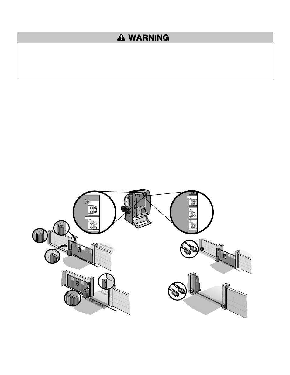
Close Sensor on Wall
Open Sensor on Wall
Close Sensor on Gate
Open Sensor on Wall
Open Sensor on Gate
ADDITIONAL
FEATURES
» ENTRAPMENT PROTECTION DEVICES
To prevent SERIOUS INJURY or DEATH from a moving gate:
• Entrapment protection devices MUST be installed to protect anyone who may
come near a moving gate.
• Locate entrapment protection devices to protect in BOTH the open and close
gate cycles.
• Locate entrapment protection devices to protect between moving gate and
RIGID objects, such as posts or walls.
CONTACT SENSORS (EDGE SENSOR)
Edge sensor models G65MG0204, G65MG0205, G65MGR205 or G65MGS205
(2-wire, non-monitored).
• CLOSE EDGE: Will detect an obstruction while the gate is closing.
• OPEN EDGE/PHOTO: Will detect an obstruction while the gate is opening.
If the electrically activated edge sensor comes in contact with an obstruction while
the gate is closing/opening, the gate will stop and reverse direction for a short time.
The gate will remain in this position until another command is given. If the edge
sensor comes in contact with the obstruction a second time, the gate will stop and
reverse direction for a short time and the operator alarm will sound. The alarm will
sound (up to 5 minutes) and the operator will have to be reset before it will resume
normal operation.
1
Connect the contact sensor wires to either the CLOSE EDGE or
OPEN EDGE/PHOTO terminal on the control board.
NON-CONTACT SENSORS (12 VDC PHOTOELECTRIC SENSORS)
Photoelectric sensor model 50-220.
It is best to use failsafe photoelectric sensors. If a photoelectric sensor is not working
or loses power or the photo beam is permanently blocked, the photoelectric sensor
will stop ALL gate operation.
• CLOSE PHOTO: If the photoelectric sensor beam is broken while the gate is closing,
the gate will stop and reverse to the fully open position. The obstruction must be
cleared before the operator will resume normal operation.
• OPEN PHOTO: If the photoelectric sensor beam is broken while the gate is opening,
the gate will stop and stay in that position until the obstruction is cleared. Once the
obstruction is cleared the operator will resume normal operation.
NOTE: The OPEN EDGE/PHOTO terminal may be used as a secondary input for
photoelectric sensors (as in dual gate applications, when more than one OPEN
PHOTO is needed).
Property owners are obligated to test photoelectric sensors monthly.
1
Connect the non-contact sensor wires to either the OPEN PHOTO or CLOSE
PHOTO terminal on the control board.
1
1
Entrapment Non-Contact Sensor
Safety Non-Contact Sensor
TO REMOVE CHAMBERLAIN PHOTOELECTRIC SENSORS
Remove the photoelectric sensor wires from the terminal block.
Press the LEARN LIMITS button.
Toggle the reset switch.
1
2
3
23