Ram 30-30, Installation specifications, Concrete pad construction – Controlled Products Systems Group RAM3030 User Manual
Page 8
6
RAM 30-30
RAMSET
www.ramsetinc.com
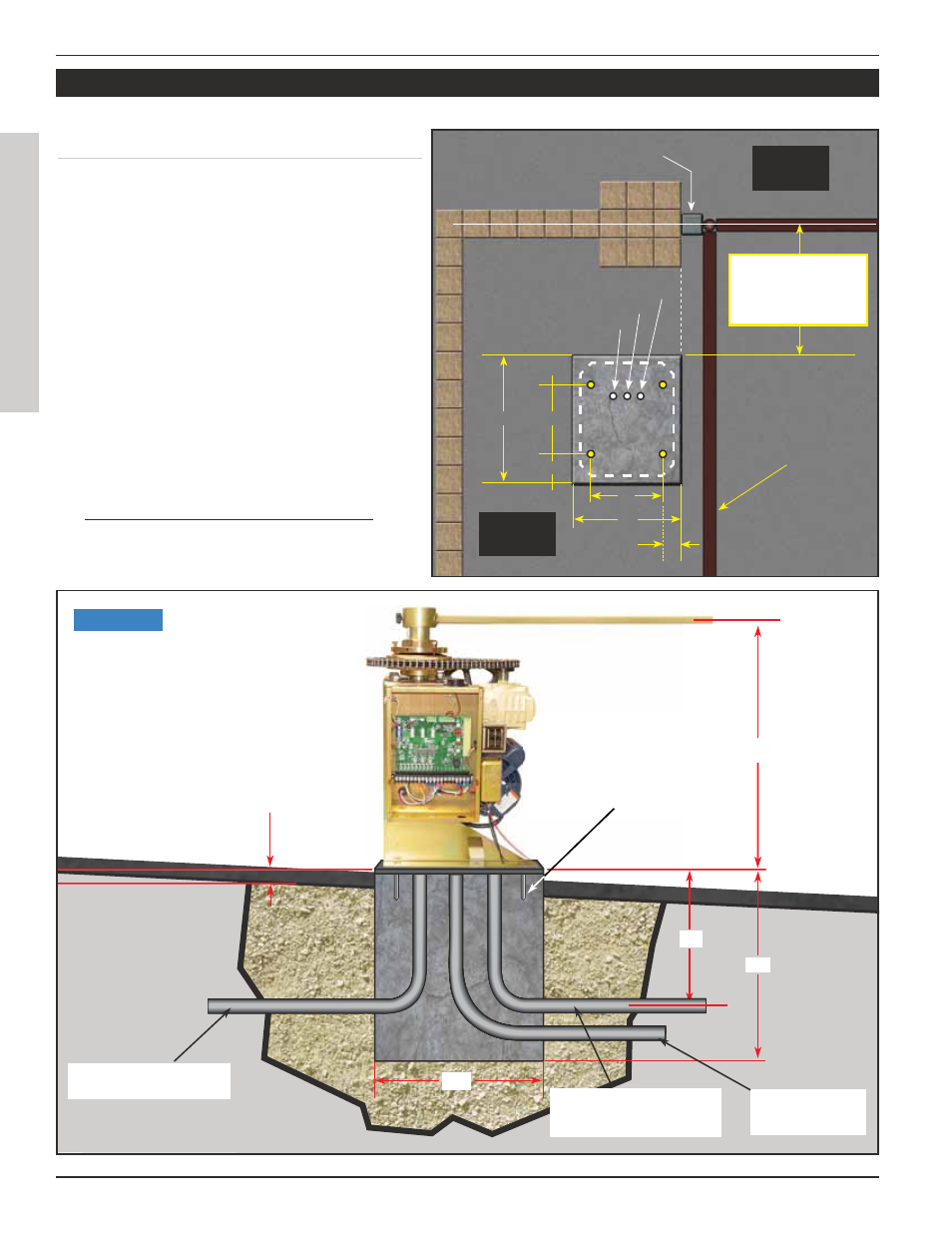
CONCRETE PAD CONSTRUCTION:
Dimensions given for the pad are based on soil
bearing shear of 2000 P.S.F. These figures may
have to be adjusted depending on local soil
conditions.
1. Construct form for mounting pad according
to dimensions shown in Figure 1 and 2.
2. Locate mounting pad according to dimen-
sions given in illustration.
3. Level top edge of form.
4. Set reinforcing bars and wire mesh.
5. Allow pad to cure for 48 hours, and remove
forms.
6. Note: conduits 6” above concrete pad.
INSTALLATION SPECIFICATIONS
GROUND LEVEL
ELECTRICAL
CONDUIT FOR
MASTER/SLAVE
DEDICATED CONDUIT
WITH 15 amp BREAKER
3/4” ANCHOR
BOLTS 4X
INDEPENDENT CONDUIT
FOR LOW VOLTAGE
WIRES
18”
18”
24”
15”
ALLOW 2” ABOVE
GROUND LEVEL
MINIMUM FOR
LEVELING.
3/4” ANCHOR
BOLTS 4X
15”
Figure 2
Gate Opened
CONDUIT FOR ELECTRIC POWER
CONDUIT FOR MASTER/SLAVE
CONDUIT FOR COMMUNICATION
Steel Square Tubing
4x4
STANDARD
INSTALLATIONS
Gates From: 8’-16’ (18”)
Gates From 16’-22’ (24”)
Inside
Property
Outside
Property
14”
2 1/2”
20”
6 3/4”
26”
13”