1 direction 2 timer, Wire receiver 4-wire receiver, Current sensor donut – Controlled Products Systems Group 9310-080 User Manual
Page 5
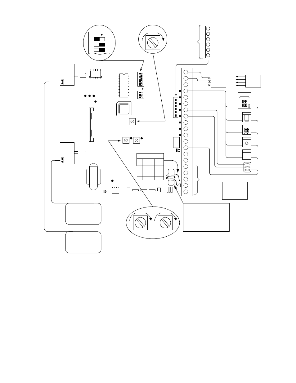
9410
9410
EXIT LOOP
REVERSE LOOP
ON
12
3
1 DIRECTION
2 TIMER
1 Open Cycle Photocell
2 Close Cycle Photocell
3 Open Cycle Contact Sensor
4 Close Cycle Contact Sensor
5 Common
6 Common
Secondary
Entrapment
Protection
Devices
CA
U
T
IO
N
16-
20 H
IGH
V
O
L
T
A
G
E
!
TIMER
REV SENS
OPEN
REV SENS
CLOSE
TIME DELAY
1
2
3 4
5
6
7
8
1 2
3 4
ON
REVERSE
LOOP
G
A
T
E
F
O
RCE
D
EA
RT
H
G
ROUND
CAP
A
C
IT
O
R
CO
NNEC
T
O
R
REV
E
RS
IN
G
D
E
V
ICE
CO
N
N
ECT
O
R
1
2
3
4
5
6
7
8
9
10
11
12
13
14
15
16
17
18
19
20
POWER
EXIT
LOOP
LIMIT SWITCH
CONNECTOR
LI
MI
T
PA
R
T
IA
L
LI
MI
T
RELAY CONTACT
CLOSE
OPEN
SENSITIVITY
24V Com
Relay
Radio Pwr
3-Wire
Receiver
4-Wire
Receiver
24V Com --
Relay
Relay
Radio Pwr +
1
1
2
3
Fire
Dept
NOTE
Terminal 1 and 13
are the same.
Either can be used
as a low voltage
common.
Current Sensor Donut
HP
Volt-Ph
Turns
1/2
1
1
1
1
All
Sgl Ph
208-3
230-3
460-3
2
1
5 *
5 *
9 *
* CURRENT SENSOR DONUT
For 1HP 3-Phase motors, the RED current
sensor wire is connected directly to the
lug opposite of terminal 19. The black
motor wire is routed through the donut
with the number of turns shown in the
table. Refer to the wire diagrams in the
back of the manual.
9310-065-F-12-07
Page
5