Wiring the manual override, Configuring the pushbutton, Seco-larm u.s.a., inc 3 – Controlled Products Systems Group SD-6276-SS1Q User Manual
Page 3: Buzzer output, Relay output mode, Led ring colors, Switch output type, Timer adjustment, Output duration is adjustable 1~30 seconds
ENFORCER Outdoor Piezoelectric Request to Exit Pushbutton
SECO-LARM U.S.A., Inc
3
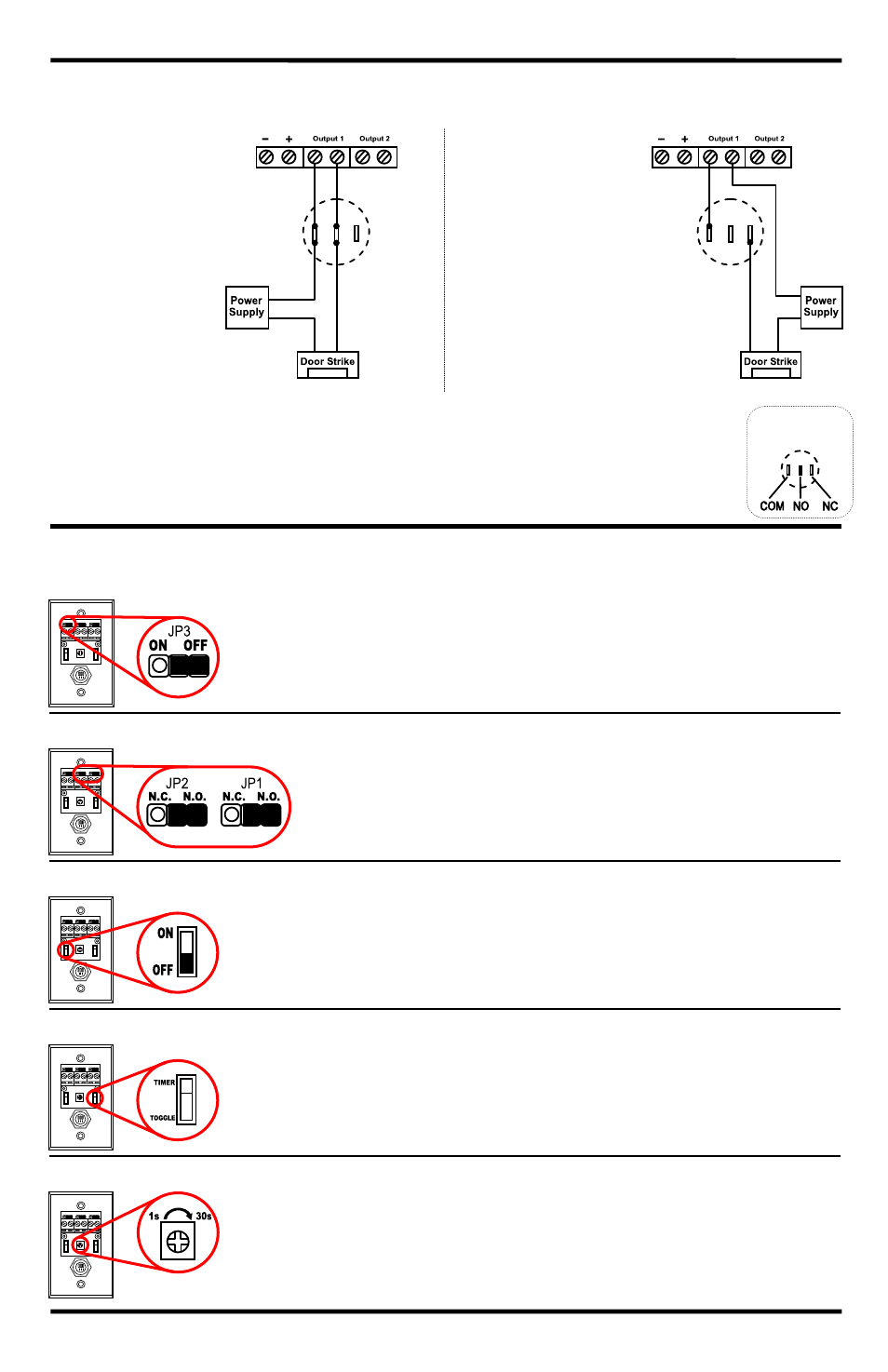
Wiring the Manual Override:
SD-6176-SSVQ and SD-6276-SSVQ Only
Connect the manual override button with the included wires.
Notes
a. Remove the thin panel on the bottom of the plastic cover to allow wiring to pass through.
b. There is only one relay, wiring the button to either output will allow the other output to trigger simultaneously.
c. Do not connect the manual override button to more than one output.
d. When wiring for either N.O. or N.C., be sure to also set the Relay Output Mode to N.O., as described below.
If Relay Output Mode and override button wiring do not match, the product may not function as expected.
Configuring the Pushbutton:
1. Buzzer Output
DEFAULT: ON
Use the buzzer output jumper JP3 to program the buzzer output.
Placing the jumper on the left turns buzzer output ON. Placing the
jumper on the right turns buzzer output OFF.
2. Relay Output Mode
DEFAULT: N.O.
Outputs 1 and 2 can be set independently using jumpers
JP1 and JP2. Note: Both outputs trigger simultaneously.
Place the jumper on the right for N.O. operation and on the
left for N.C. operation.
3. LED Ring Colors
DEFAULT: OFF
ON: LED is green while in standby, and turns red when triggered.
OFF: LED is red while in standby, and turns green when triggered.
4. Switch Output Type
DEFAULT: Timer
TIMER: When set to TIMER, pressing the switch will trigger the relay for
the set time. Set the time using the trimpot as described above.
TOGGLE: When set to TOGGLE, pressing the switch will cause the
relay to trigger until the switch is pressed again.
5. Timer Adjustment
DEFAULT: 1s
Output duration is adjustable 1~30 seconds.
(Must be set to ‘Timer’ in step 4
)
Gently rotate the trimpot using a Philips head screwdriver.
Counterclockwise decreases the output time.
Clockwise increases the output time.
Wiring For N.O.:
Connect the two
wires between the
NO and COM
terminals of the
override button and
the Output 1 or 2
terminals on the
switch.
Wiring For N.C.:
Connect the two
wires between
the NC and COM
terminals of the
override button
and the Output 1
or 2 terminals on
the switch.
N.O.
COM
N.C.
COM
Manual
Override Button