Sub-category jumpers e1-e8 “a” side, Adjacent relay drive jumpers e17-e23, Ategory – CTI Products RYB-8 Relay Board User Manual
Page 7: Umpers, E1-e8, A” s, Djacent, Elay, Rive, E17-e23
CTI Products, Inc.
MCN RYB-8 Relay Board Manual
3
68-11206-100
2.2
Sub-Category Jumpers E1-E8 “A” Side
When you use the MCN Relay Board with an MCN IOB module and the
MCNRCD PC Software, you can use the “A” side of jumper blocks E1 through
E8 to provide static sub-category status text selections. This will allow you to
specify different status text messages (On/Off, Up/Down, Main/Standby, etc. as
defined in the MCNRCD.CFG file) for different relays on the MCN-RYB-8
board.
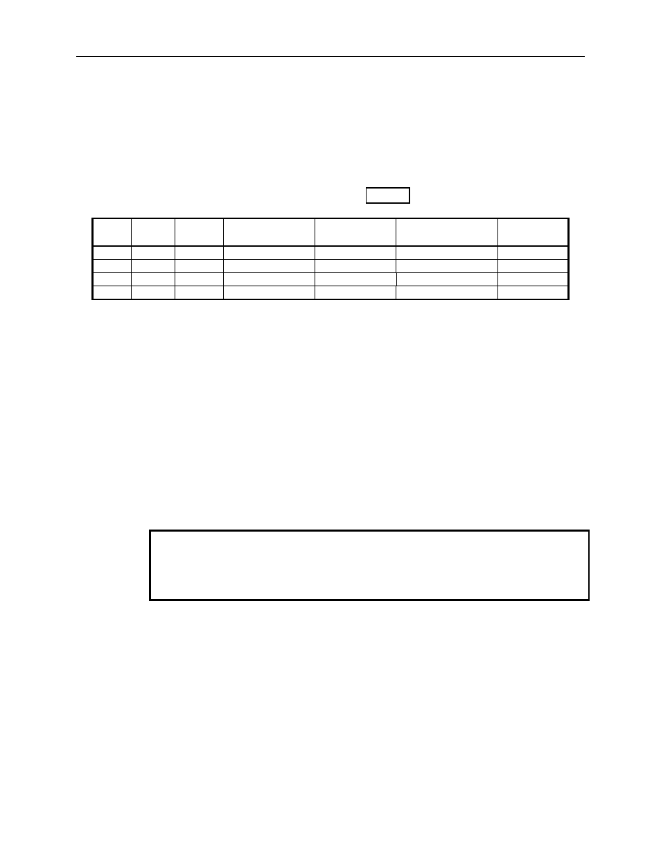
For relay K1, the jumpering is shown in Table 1:
J2
Pin
Relay
I/O Bit
Jumper
CIB Signal
IOB Mode 1
Signal
MCNRCD
Bit Weight
21
1
1
E1-A1 In
VOTE 1
Input/Output 1
1
22
1
2
E1-A2 In
RECEIVE 1
input 1
04
20
1
3
E1-A3 In
DISABLE 1
Input/Output 9
10
23
1
4
E1-A4 In
FAIL 1
input 9
40
Table 1 - Sub-Category Jumpers
Since I/O bit 1 is normally used to control the relay, I/O bits 2-4 are available for
sub-category selection. Up to (8) sub-categories can be configured with these 3
bits. When a jumper is inserted, the bit is active. See the MCNRCD Software
Manual and IOB hardware manual for more details on sub-categories.
2.3
Adjacent Relay Drive Jumpers E17-E23
In some applications you may need to drive two relays from the same input signal.
You can use jumpers E17-E23 to connect a relay's coil to an adjacent relay's coil.
E17 jumpers the coils for relays 1 & 2 together. E18 jumpers relays 2 & 3, and so
on.
Caution
When you insert the Adjacent Relay Drive jumpers (E17-E23), be sure that you
have only one input active (E1-E8 "B" side) for each set of relays that are
connected together.
These jumpers are normally not installed from the factory, unless a custom
configuration is ordered.