How the system works, Multiple displays, Dial-up applications – CTI Products GPIO General Purpose I/O Interface User Manual
Page 2: General specifications, Models, Gpio – general purpose interface module
GPIO – General Purpose Interface Module
GPIO 2008-06
MCN, MCNRCD, CIB, HIB,and EXB are trademarks of CTI Products, Inc.. Windows, Windows NT, 2000, XP are trademarks or registered trademarks of Microsoft.
Other trademarks referenced are properties of their respective owners. Specifications subject to change or improvement without notice.
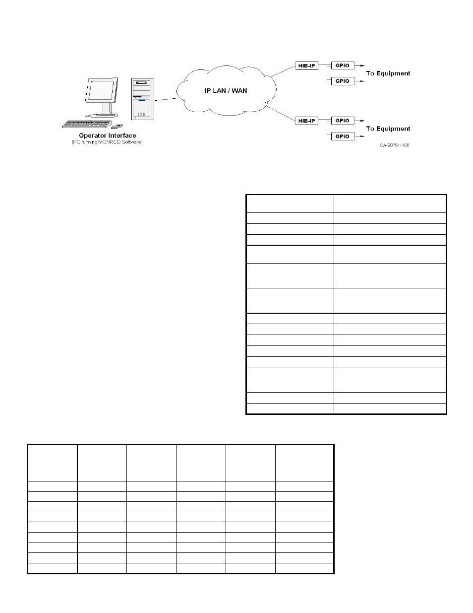
Typical MCN Monitor & Control System
How the System Works
The MCN Monitoring & Control Network includes two basic
parts: Interface Modules and the Operator Interface.
The Interface Modules mount near the equipment to be
monitored or controlled. They pass the status indications from
the equipment to the MCN network for display on a PC. The
Interface modules also accept control commands from the
network and generate signals to control equipment inputs.
The status information from Interface Modules is passed over
the network to Operator Interfaces. The diagram shows a PC
(with MCN RCD™ Software) connected to GPIO modules via
an IP network and HIB-IP modules.
As shown above, the PC can control and monitor equipment at
multiple sites. In addition to using an IP LAN or WAN to
remotely monitor and control equipment, other channels can be
utilized such as PSTN, Microwave, and Channel Banks.
Multiple Displays
The MCN System offers full parallel status and control at
multiple PC Operator Interfaces. PC Displays and Console
Displays may be mixed in a single system with some
limitations.
Dial-Up Applications
For maintenance purposes, a PC display can be used over
dial-up lines with HIB-232 modules. Technicians can remotely
diagnose system problems from home using a properly
equipped PC and dial-up modem.
General Specifications
Size (MCN Size A)
5.5" x 4.2" x 1.5"
(140 x 107 x 38 mm)
Weight
16 oz, (455 g)
Temperature 0-50
o
C
Humidity
10- 95% non-condensing
Inputs Optically
Isolated
12 – 24 VAC/VDC
Outputs for
Solid State Relay Models
Optically Isolated
SPST (Form A)
24 VAC/VDC, 1 A Max. Resistive
Outputs for
Electro-Mechanical Relay
Models
SPDT (Form C)
48 VAC/VDC, 1 A Max. Resistive
Inputs & Outputs per Module
See Models table
Indicators
One LED for each input & output
Equipment Connector
50 pin Telco style, Female
Network Connectors
(2) RJ-45 (1 in, 1 out)
Maximum Network Segment
4000 ft. without repeaters
Maximum Interface Modules
16 per network segment
(Larger, multi-segment systems can
be custom-configured.)
Network Cabling
4 Pair Level 4 UTP
Power Input
12 to 30 VDC / 2 W
Models
Part
Number
Model
Opto-
Isolated
Inputs
SSR
Outputs
(Form A)
E-M Relay
Outputs
(Form C)
Magnetically
Latched Relay
Outputs
(Form C)
S2-61281 GPI-12
12
S2-61282 GPI-24
24
S2-61283 GPO-12A
12
S2-61284 GPO-24A
24
S2-61285 GPIO-1212A
12
12
S2-61299 GPIO-1208C
12
8
S2-61363 GPO-16C
16
S2-61426 GPIO-1208L
12
8
S2-61437 GPO-16L
16
Other I/O combinations are
available; consult factory for
part number.