Iib input/output interface module – CTI Products IIB Console Interface User Manual
Page 2
IIB Input/Output Interface Module
II B 2005-08
MCN, MCNRCD, IIB, CIB, AIB, EXB and HIB are trademarks of CTI Products, Inc.. Motorola and ASTRO-TAC are trademarks of Motorola.
Other trademarks referenced are properties of their respective owners.
Specifications subject to change or improvement without notice.
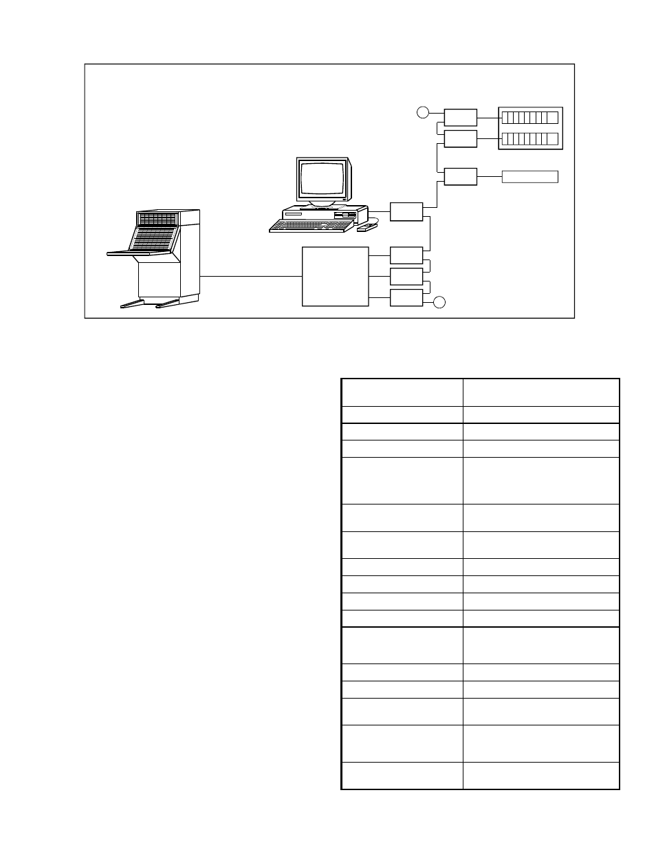
The How the System Works
The MCN Remote Comparator Display includes two basic
parts: the Comparator Interface Modules and the Operator
Interface.
The Comparator Interface Modules (CIBs and AIBs) mount
near the comparator. They pass the Vote, Receive, Disable,
and Fail signals from the voting comparator to the MCN
network.
The receiver data is passed over the network to Operator
Interfaces, such as HIBs and IIBs. The diagram shows PCs
connected to the network via HIB Host Interface Modules.
Consoles are connected via IIB I/O Interface Modules.
The Operator Interfaces (HIBs and IIBs) accept Force-Vote
and Disable signals from the PC or console and generate
Force-Vote and Disable commands on the network.
The comparator interface modules (CIBs and AIBs) accept
Force Vote and Disable commands from the network and
generate
the
Force
Vote
and
Disable
signals
to
the
comparator.
Multiple Displays
The IIB modules will typically be connected at one location to
central console electronics. The console system then provides
multiple console display & control positions. PC Displays and
Console Displays (HIBs and IIBs) may both monitor & control
a single comparator with some limitations.
Other MCN System Products
The IIB Input/Output Module is just one module in the MCN
series.
Other modules may be used for other control,
monitoring, and alarm applications.
Call our Systems
Engineers to find out how an MCN Comparator Display
System can be configured to fit your specific needs.
General Specifications
Size (MCN Size A):
5.5" x 4.2" x 1.5"
(140 x 107 x 38 mm)
Weight:
16 oz, (455 g)
Temperature:
0-50
o
C
Humidity:
10- 95% non-condensing
Receivers controlled:
8 per IIB (Selectable in banks for
connection to AIBs. Two IIBs are
required to monitor and control 16
receivers on an AIB.)
Bi-directional Inputs /
Outputs per receiver:
2: Vote (Force Vote) and Disable
Outputs per receiver:
2: Force Vote, Disable
Logic Levels, active low
Max I/O voltage:
+30 VDC
Comparator Connector
50 pin Telco style, Female
Network Connectors:
(2) RJ-45 (1 in, 1 out)
Max. network segment:
4000 ft. without repeaters
Max. IIB modules:
40 per network segment
(Larger, multi-segment systems can
be custom-configured.)
Network Cabling
4 Pair Level 4 UTP
Power Input
12 to 30 VDC / 2 W
Safety Approvals to:
UL 1950, CSA 1950
EN60950-1992 (CE)
Emissions Compliance:
FCC part 15, Class A
IC (DOC), Class A (Canada)
EN55022, Class A
Susceptibility Compliance:
IEC 801-2, 3, 4
EN50082-1
Typical MCN Remote Comparator Display System
COMPARATOR
ASTRO-TAC
CIB
CIB
AIB
T
HIB
IIB
IIB
IIB
T
CONSOLE
ELECTRONICS
TAC or EGE
COMPARATORS
DIGITAC, Spectra-TAC
CONSOLE