A" "b – American Standard 1480SS.500 User Manual
Page 2
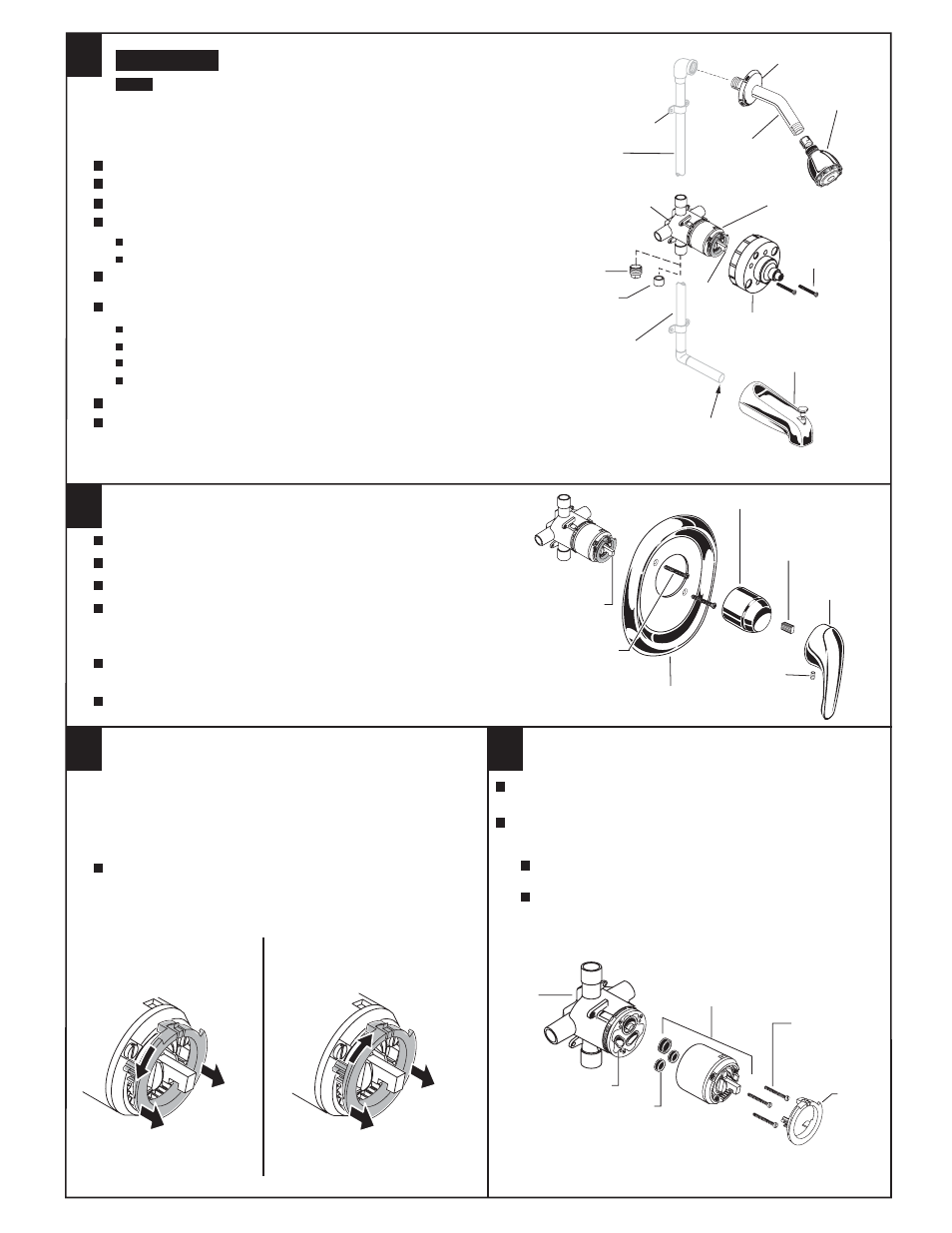
INSTALL TRIM
1
2
CARTRIDGE
STEM
ADJUSTMENT WHEN
WATER IS TOO HOT
ADJUSTMENT WHEN
WATER IS TOO COLD
PRY FORWARD TO UNLOCK
AND ROTATE COUNTER-
CLOCKWISE ONE CLICK
PRY FORWARD TO UNLOCK
AND ROTATE CLOCKWISE
"A"
"B"
By restricting handle rotation and limiting the amount of hot
water allowed to mix with the cold, the HOT LIMIT SAFETY
STOP reduces risk of accidental scalding. To set the maximum
hot water temperature of your SEVA faucets, all you need
to do adjust the setting on the HOT LIMIT SAFETY STOP.
Remove HANDLE, CAP and HOT LIMIT STOP. Follow "A" or "B"
to adjust maximum discharge temperature.
SERVICE
4
3
HOT LIMIT STOP
When finished, tiling the wall, remove PLASTER GUARD.
Push on CAP.
Mount ESCUTCHEON with SCREWS.
Install HANDLE by pushing it onto
CARTRIDGE STEM and tightening
SET SCREW from below.
Install SHOWER ARM with FLANGE and SHOWER HEAD.
Install SPOUT.
Check proper operation of HANDLE
and DIVERTER SPOUT.
SPOUT
SHOWER
ARM
SHOWER
HEAD
TUB FILLER TUBES*
(5/8" O.D. -
1/2"
NOMINAL)
BODY
STEM
SCREWS
RISER
PIPE *
BRACE (4) *
FLANGE
PLASTER
GUARD
* NOT INCLUDED
IN KIT
REMOVE BURRS
FROM TUBE
Turn off water at MAIN supply. To prevent damage temporarily
remove STOPS when water supply lines are soldered to the manifold.
CAUTION
ROUGHING-IN
Connect hot and cold water supplies.
For support, use pipe BRACES secured to wooden braces.
With valve turned off, turn on water supplies and check for leaks.
See Roughing-in diagram on reverse side.
Connect RISER PIPE to MANIFOLD top outlet marked "SHR".
Connect TUB FILLER PIPE at bottom outlet marked "TUB".
Supply connections are:
1/2" copper sweat for sweat inlets.
1/2" female NPT for threaded inlets.
For proper positioning the finished wall must be within side wall of PLASTER GUARD.
If the valve is installed on a fiberglass or other thin wall application, the PLASTER GUARD can
be used as a support:
Cut a 3" dia. hole in the shower stall.
If stops are used drill two additional 1" holes to allow access to the stops.
Remove PLASTER GUARD, rotate 180˚ so that indicated screw holes fit manifold.
Push CAP on valve, place ESCUTCHEON and attach with screws.
ESCUTCHEON
SCREWS
ESCUTCHEON
METAL
LEVER
HANDLE
CAP
SET
SCREW
HANDLE
BUSHING
COLD
HOT
CARTRIDGE
Remove HANDLE, CAP, HOT LIMIT STOP and CARTRIDGE.
Clean inlets and MANIFOLD.
Reassemble CARTRIDGE, alternately tightening screws. Replace
HOT LIMIT STOP , CAP and HANDLE. Check flow.
If faucet drips, operate handle several times from "off" to "on".
Do not apply excessive force.
Clogged CARTRIDGE inlets may cause reduced flow in "full
on" hot or cold. To clean inlets, first turn off water supply,
then:
VALVE
BODY
MANIFOLD
CARTRIDGE
SEALS
CARTRIDGE
HOT LIMIT
STOP
CARTRIDGE
MTG. SCREWS
PLUG
(NPT)
PLUG
(SWEAT)
M968395 Rev. 1.1
When soldering, remove PLASTER GUARD, CARTRIDGES and CHECK STOPS (IF PRESENT). When
finished soldering, flush valve body, replace cartridges, check stops (if present) and plaster guard
to continue installation. Use thread sealant or Teflon tape on threaded connections
NOTE