Comprehensive CDA-VGA41 User Manual
Page 7
5
Table 3: Features and Functions of the CDA-VGA41 1:4 High Resolution XGA DA
# Feature
Function
1 12V DC
+12V DC connector for powering the unit
2 OUTPUT 1 HD15F Connector Connect to the XGA acceptor 1
3 OUTPUT 2 HD15F Connector Connect to the XGA acceptor 2
4 INPUT HD15F Connector
Connect to the XGA source
5 OUTPUT 3 HD15F Connector Connect to the XGA acceptor 3
6 ON LED
Illuminates when receiving power
7 OUTPUT 4 HD15F Connector Connect to the XGA acceptor 4
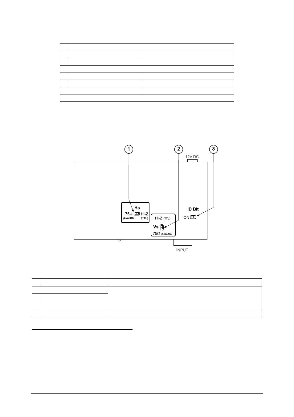
4.4 Your High Resolution XGA DA Underside
Figure 4 and Table 4 define the switches on the underside of the High
Resolution XGA DA:
Figure 4: High Resolution XGA DA Underside
Table 4: High Resolution XGA DA Underside Features
# Feature
Function
1 Hs (Horizontal Sync) Switch
2 Vs (Vertical Sync) Switch
Set both switches
1
to Hi-Z (TTL
2
) if the source is, for example, a
digital graphics card. Set both switches to 75 (ANALOG) if the
source is analog based, for example, an RGBHV source with coaxial
cable for sync
3 ID Bit Switch
Slide to the left to set to ON
3
; to the right to set to OFF
4
1 Both the Hs and the Vs switches MUST be set identically (no harm will occur to the graphics source if the switches are set
to the wrong direction)
2 “Transistor-Transistor Logic” is a term used in digital electronics describing the ability of a device or circuit to be connected
directly to the input or output of digital equipment. Such compatibility eliminates the need for interfacing circuitry
3 Enabling the notebook or laptop to output a VGA signal to an external VGA monitor
4 When the source is not a laptop (for example, a PC)