CNB MXC6050IR User Manual
Page 11
M
M
X
X
C
C
6
6
0
0
5
5
0
0
I
I
R
R
U
U
s
s
e
e
r
r
’
’
s
s
G
G
u
u
i
i
d
d
e
e
Rev.1.0 (Dec. 2013)
11
2.4. Functional Description
Power : Power input for supplying 12V DC, 1A power.
Caution :
If MXC6050IR is powered by PoE, do not plug in DC Jack with active DC
power into DC power connector.
Network (LAN)
100Mbps Ethernet connector (RJ-45) with PoE standard (802.3af). LED on the Ethernet connector shows the
status of MXC6050IR as the followings:
- Status LED (It will be lit in green or red depending on the status)
① Green : Green color indicates that the camera is in normal operation mode. Continuous green
indicates that data transmission is possible. Blinking green means that someone is connected to
MXC6050IR.
② Red : Continuous or blinking red indicates that hardware is in abnormal condition.
MIC/Line Input
Connect external audio source or microphone.
Line Output
Connect speakers with built in amplifier. Audio from remote site is output through Line out in bi-directional
audio mode.
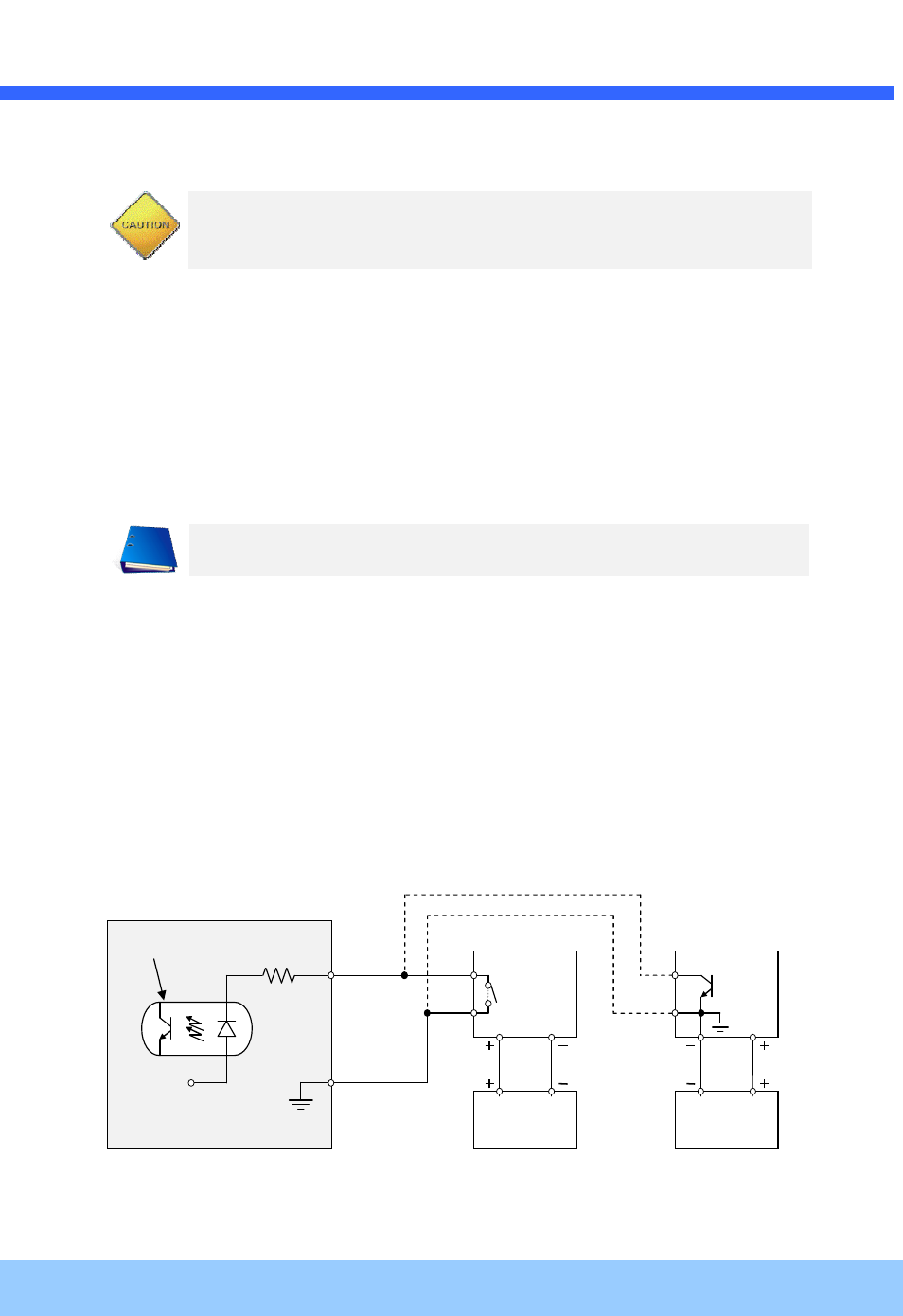
Sensor Input
Connect external alarm sensor. Examples of sensing devices are infrared sensor, motion sensor, heat/smoke
sensor, magnetic sensor, etc. Connect the two wires of the sensors to “SNS In”. The sensor type(NC/NO)
can be set in admin page. Multiple sensor devices can be connected in parallel.
Figu
re 2-4. SENSOR input and connection of the sensor
LED will be lit with red momentarily and it will be lit with green after a while when power is
applied into MXC6050IR
Photo Coupler
NO/NC Type
Open Collector Type
Sensor1+
Sensor
Device
Sensor1-
Sensor
Device
Sensor
Power
Supply
Sensor
Power
Supply
GND
+12V