Electrical information – Cleveland Motion Controls Current Regulator PowerBlock2 MO-13829 User Manual
Page 2
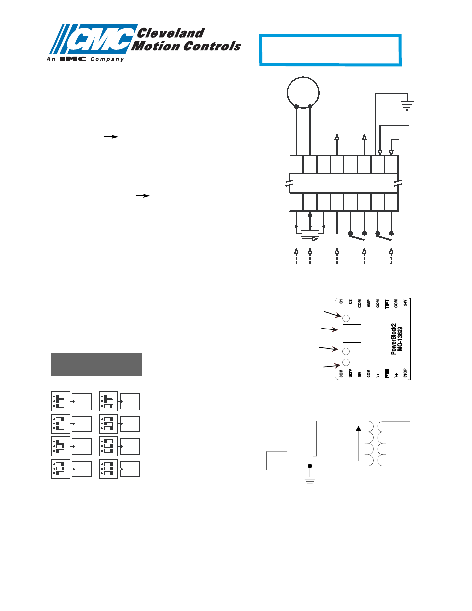
Electrical Information:
Connections
C1 / C2
Brake/Clutch
Com 0
V
Amp
Real time current equivalent voltage
(1.00 A 1.00 V)
Test
Internal fuse test points
(When OFF, measure of 10K
Ω
Ω
between the two (2) points (*) means that the fuse is OK
Com Equipotential supply point (when grounding the
transformer secondary)
24 V
Input Power : 24 V AC or 24 V DC
SetP Set point input (0 10 V DC)
10 Set point potentiometer supply (10 k
Ω
Ω
)
V+ Logic inputs voltage
Free Logic input “Freewheel” mode
Stop
Logic input “Holding” mode
Front face LED’s
L1
Power ON
L2
Freewheel mode active
L3
Holding mode active
Switches
S1 S2 S3 Max current adjustment
(from 0.25 to 2.00 A, for set point input = 10 V)
Note :
- The equipotential point is available on terminal “Com” of
the supply terminals
- When grounding the secondary of the transformer, refer to the Transformer Grounding diagram above
PowerBlock2
MO-13829
Brake/
Clutch
0 V
+24 V
AC / DC
A
1
=
V
1
10 k
Ω
0 - 10 V
0 V
+24 V
+24 V
t
s
e
T
e
s
u
F
1
C
2
C
m
o
C
p
m
A
t
s
e
T
V
4
2
Pt
e
S
V
0
1
+
V
e
er
F
+
V
p
ot
S
m
o
C
m
o
C
m
o
C
m
o
C
L1
L2
L3
Switches
*
*
0.25
0.50
0.75
1.00
1.25
1.50
1.75
2.00
Max. Output current
adjustment
Primary
Secondary
Com
24V
©Cleveland Motion Conrols, Inc.
7550 Hub Parkway • Cleveland, Ohio 44125
ph: 216.524.8800 or 800.321.8072 • fax: 216.642.2199
www.cmccontrols.com • email: [email protected]
Transformer Grounding diagram
Off On
Off On
HOLDING
# AO-70321 7/04
FREEWHEEL
CURRENT
SCALING
POWER