2 output wiring, 1 digital voltmeter, Output wiring – Cleveland Motion Controls Classic Series DIN Rail Amplifier Non-Isolated MWI-13466 REV CA User Manual
Page 15: Ca c
MAN-13466
R
EV
CA C
LASSIC
S
ERIES
N
ON
-I
SOLATED
A
MPLIFIER
P
AGE
15
OF
26
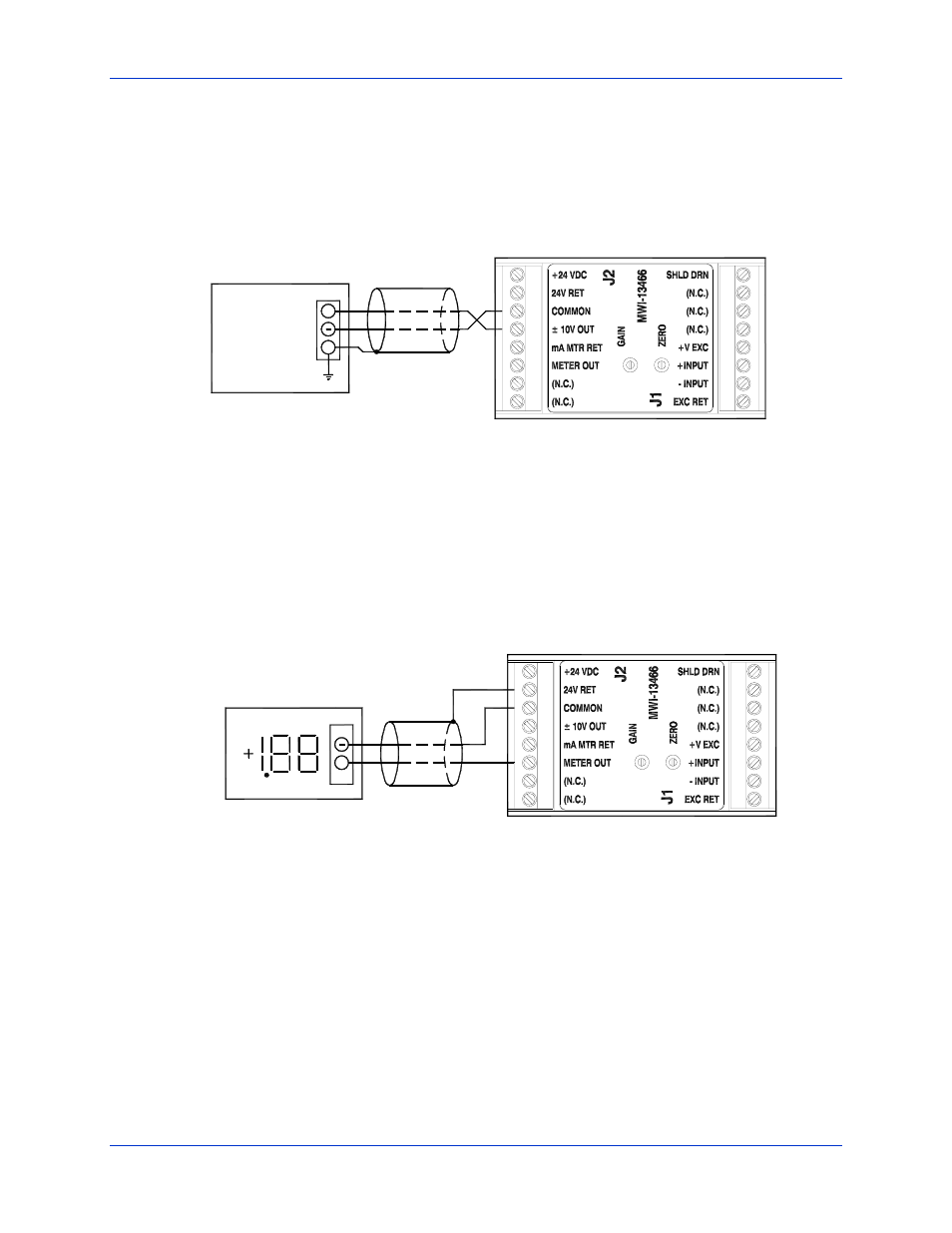
2.12.2 O
UTPUT WIRING
The load in this connection may be an indicator, recorder, data acquisition device or the analog input terminals of a
control device such as a DC drive or a programmable logic controller. The output signal at this terminal is
undamped and is the output terminal that provides that fastest response to changes in the transducer (load-cell) load.
Note that the cable’s shield drain wire should be connected at only one end, preferably at the “receiving end”.
8
7
1
2
3
5
6
4
2
1
6
4
3
5
7
8
SHIELD GND
RESISTANCE
5000 OHM MIN
+ / - 10V LOAD
+
Figure 7 - Output Wiring, +/- 10V Analog
2.12.2.1 D
IGITAL
V
OLTMETER
The +/- output terminal is designed to provide +2.0 volts when the +/- 10 V output terminal is adjusted (with the
Gain and Zero pots) to be +10.0 volts (this is full scale). To achieve different scaling, adjust gains on the Digital
Panel meter (DPM).
DIGITAL VOLT METER
+
7
8
2
1
3
4
6
5
1
2
8
7
5
3
4
6
0 TO 1.99 VOLT
MINIMUM METER RESISTANCE = 2000 OHMS
Figure 8 -
Output Wiring, Damped +/- 2V Analog