12 the power supply, 1 power wiring diagram, Ower – Cleveland Motion Controls Classic Series DIN Rail Amplifier Non-Isolated MWI-13466 REV CA User Manual
Page 14: Upply, Power wiring diagram, 12 t
C
LASSIC
S
ERIES
N
ON
-I
SOLATED
A
MPLIFIER
MAN-13466
R
EV
CA
P
AGE
14
OF
26
•
Do not pre-tin the stranded wires inserted into the pluggable connector.
•
A stable connection relies on the springy nature of stranded conductors to ensure a low contact
resistance despite thermal cycling and airborne impurities.
•
Avoid temperature extremes or gradients where electrical connections are made between different
metals. Connections can cause thermocouple voltages to be generated, which then become
superimposed on transducer signals.
•
In severe cases, additional shielding may be required in the form of either external flexible braided
shields or running the field wiring wires inside metallic conduit
.
2.12 T
HE
P
OWER
S
UPPLY
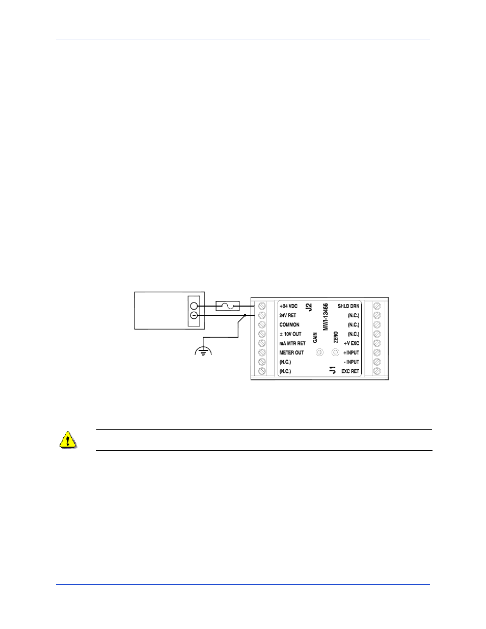
For best performance a regulated power supply should be used with the Classic Series DIN Rail amplifier. It is
important that you pay particular attention to the power supply for susceptibility to the effects of conducted and
radiated energy from noise sources. Every effort should be made to provide stable voltage to the amplifier using
correct wiring practices and filters. To protect against circuit damage, include a 0.38 Amp fuse in the power supply
output lead to each amplifier in case of amplifier or power supply malfunction.
2.12.1 P
OWER
W
IRING DIAGRAM
The 0.38 A fuse in the +24VDC power lead is required for protection of the amplifier in the event of amplifier or
power supply malfunction.
8
7
5
6
3
4
2
1
1
2
3
4
6
5
7
8
+
24 V
0 V
FUSE
24 Vdc
POWER
SUPPLY
Figure 6 - Wiring diagram for use with 24 VDC power supply
The power source for the power supply shall be fused at the proper rating to prevent over current in
the supply leads due to a power supply failure.