5 configuring the switch settings, Onfiguring the, Witch – Cleveland Motion Controls Classic Series DIN Rail Amplifier Non-Isolated MWI-13466 REV CA User Manual
Page 11: Ettings, Ca c
MAN-13466
R
EV
CA C
LASSIC
S
ERIES
N
ON
-I
SOLATED
A
MPLIFIER
P
AGE
11
OF
26
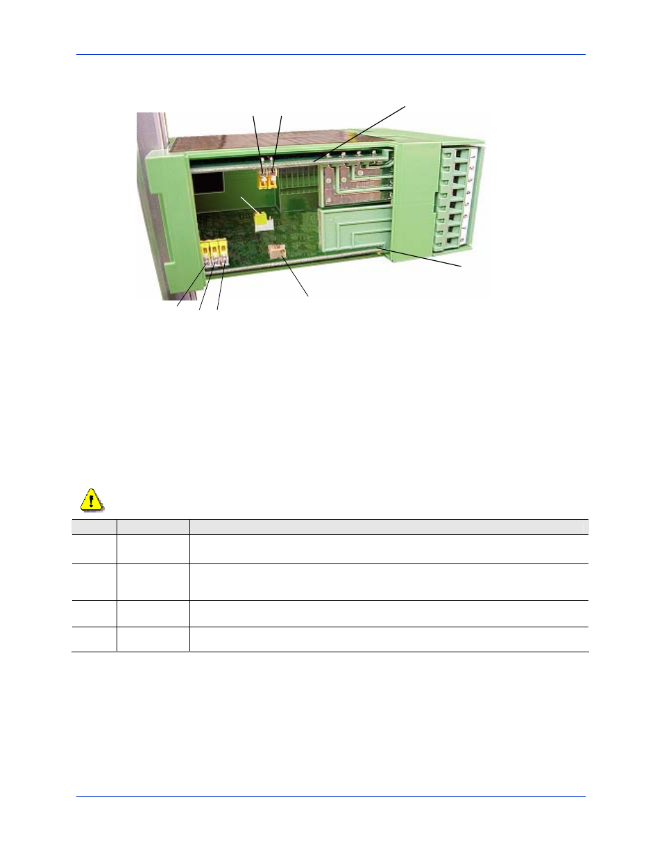
Figure 4 - Internal Jumper-switches and Potentiometer Location
2.5 C
ONFIGURING THE
S
WITCH
S
ETTINGS
A number of operational characteristics can be configured prior to mounting or wiring the amplifier. We
recommended that you first familiarize yourself with the internal switch locations, settings, and potentiometers by
opening the snap-on access cover. Figure 4 illustrates the location of configurable items on each of the printed
circuit boards.
Use an approved anti-static wrist strap when adjusting any switch settings/potentiometers on the amplifier.
Switch
PCB Location
Function
J3
Input
Configures Excitation voltage for 5.0 or 10.0 VDC. The amplifier is factory set at (setting 1-2) for
5.0V
J10
J9
J7
Input
Sets voltage gain of the Instrumentation amplifier to 5, 25, 125 or 620. The jumper switches are
factory set to (1-2) for minimum gain (Av = 5). Refer to section 2.8 for more information on setting
Gain select switches.
J1
Output
Configures meter output stage for +/- 2V F.S. or +/- 1 mA F.S. The jumper switch is factory set for
voltage output (1-2). Voltage and current modes use different terminals.
J2
Output
Selects meter damping 0.3 Hz or 3.7 Hz. The jumper switch is set to (2-3) for minimum damping.
(3.7 Hz)
J10
J9 J7
P5
Coarse Zero
Input
Board
Output
Board
J2
J1
J3
I/A Gain