Nstalling the, Antilevered, Ransducer – Cleveland Motion Controls ULTRA SERIES CANTILEVER TRANSDUCER CLTSCM REV AA User Manual
Page 13
MAN-70252R
EV
.
AA
U
LTRA
S
ERIES
C
ANTILEVER
T
RANSDUCER
P
AGE
13
OF
18
3 I
NSTALLING THE
C
ANTILEVERED
T
RANSDUCER
The following sections provide you with detailed information and steps to correctly install the Ultra Series
Cantilevered Transducer for use with stationary shafts.
3.1 M
OUNTING THE
T
RANSDUCER
The mounting surfaces for the transducer should be flat. Remove any loose paint, rust or scale from the machine
frame before mounting.
Table F – Steps for Mounting an Ultra Series Transducer
If you are using this
type of Mounting
style:
Then, perform these steps:
Stud (S)
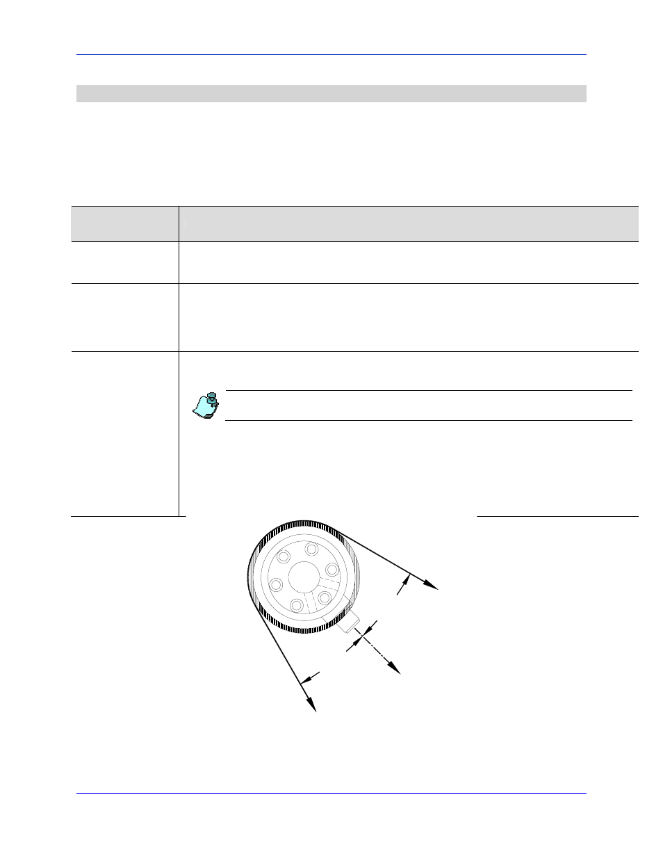
Before tightening the mounting bolt, rotate the transducer body until the force direction (indicated by the LOAD LINE
on the label) is aligned with the vector of the web force. The vector of the web force is the bisector of the wrap angle.
Refer to Figure 4 and Figure 5.
Pillow Block and
Bearing Replacement
(PB, BR)
1. Loosely mount the transducer by lightly tightening the four (4) socket head cap screws that hold the lock plate to
the back of the transducer.
2. Rotate the body of the transducer body until the direction of the force (indicated by the LOAD LINE on the label)
is aligned with the vector of the web force. Refer to Figure 4 and Figure 5.
3. Tighten the four (4) socket head cap screws to securely clamp the transducer in position.
Flange (F)
1. Before drilling the four (4) mounting holes, contemplate the orientation of the transducer taking into
consideration the location of the mounting screws. Be sure that the screws do not interfere with the position of
the connector. An optimal location for mounting holes also lets you maximize rotational alignment range.
Do not use the flange assembly as a drill template while not mounted to the transducer. The spacing
between flange halves is different when the transducer body is added.
2. Adjust the alignment of the transducer. First, be sure that the four (4) flange bolts are loose and then, loosen the
two (2) bolts that draw the flange halves together.
3. Rotate the body of the transducer body until the direction of the force, indicated by the LOAD LINE on the label,
is aligned with the vector of the web force. Refer to Figure 4 and Figure 5.
4. Secure the flange to the transducer. Tighten the two (2) socket head cap screws that draw the flange halves
together.
5. Tighten the four (4) bolts that draw the flange to the mounting surface.
LOAD
DIRECTION
WRAP
ANGLE
BISCETOR
W
E
B
WRAP
ANGLE
BISECTOR
W
EB
Figure 4 - Proper Orientation of the Cartridge Transducer