Cashco 2296HF User Manual
Page 10
10
IOM-2296
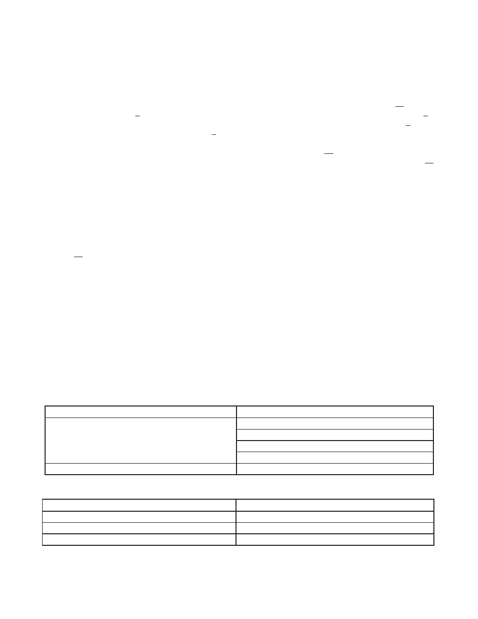
Possible Cause
Remedy
A. Excess packing friction.
A1. Realign body–stem–actuator.
A2. Packing follower too tight.
A3. Install Positioner.
A4. Increase bench.
B. Installed backwards.
B. Install per fl ow arrow.
Possible Cause
Remedy
A. Excess pressure drop.
A. Bring pressure drop within design limits.
B. Bushing wear.
B. Replace bushing and stem.
C. Misalignment.
C. Realign body-stem-actuator.
2. Valve makes "screeching" noise.
1. Valve is "jumpy" in stroking
VII. TROUBLE-SHOOTING GUIDE
SECTION VII
a. Rotate both jam nuts (17) down to base of
threads on stem (4) and tighten together.
b. Decrease pressure in the actuator to
approximately mid range of the bench
setting.
c. Rotate upper jam nut CW to increase the
combined stem length. DO NOT allow
actuator stem (6) to rotate in the actuator.
d. Rotate upper jam nut CCW to hold indi-
cating washer (16) up against stem (6).
e. Release all pressure from the actuator
and repeat Step 4 previous.
7. After the closed set point pressure has been
established, rotate lower jam nut (17) CCW
up tight under the upper jam nut.
8. Increase pressure in the actuator to the upper
pressure level of the bench setting.
9. Examine the location of the in di ca ting washer
(16) to the "C" mark on the in di ca tor plate
(23), mak ing sure to use the “top edge” of
the in di ca ting washer (16) as the ref er ence
point. Adjust indicator plate as needed.
10. Decrease pressure in the actuator until the
indicating washer (16) is in alignment with the
"O" mark on the indicator plate.
11. To limit the up travel at the desired stroke
length, rotate the travel stop nut (52) CW and
secure to bottom of the attachment hub (4).
NOTE: Secure the actuator stem (6) by the
fl ats when rotating the travel stop nut.
NOTE: “Stroke” length is in di cat ed on the
name plate (40), and is the dis tance be tween
the “C” and “O” points of the indicator plate (23).
NOTE: The proper calibration of the ac tu a tor/
valve unit will occur when at the upper pres-
sure level of bench setting, the valve plug (4)
will be in the "C" po si tion. At the lower level
of bench set the actuator pressure should be
within ± 8% of the lower bench setting for the
designed stroke length.
12. Release all pres sure from actuator.