Description of assembly procedure – CAME Gard12 User Manual
Page 5
- pag.
- pag.
- pag.
- pag.
- pag.
5
5
5
5
5
- english -
- english -
- english -
- english -
- english -
DESCRIPTION OF ASSEMBLY PROCEDURE
DESCRIPTION OF ASSEMBLY PROCEDURE
DESCRIPTION OF ASSEMBLY PROCEDURE
DESCRIPTION OF ASSEMBLY PROCEDURE
DESCRIPTION OF ASSEMBLY PROCEDURE
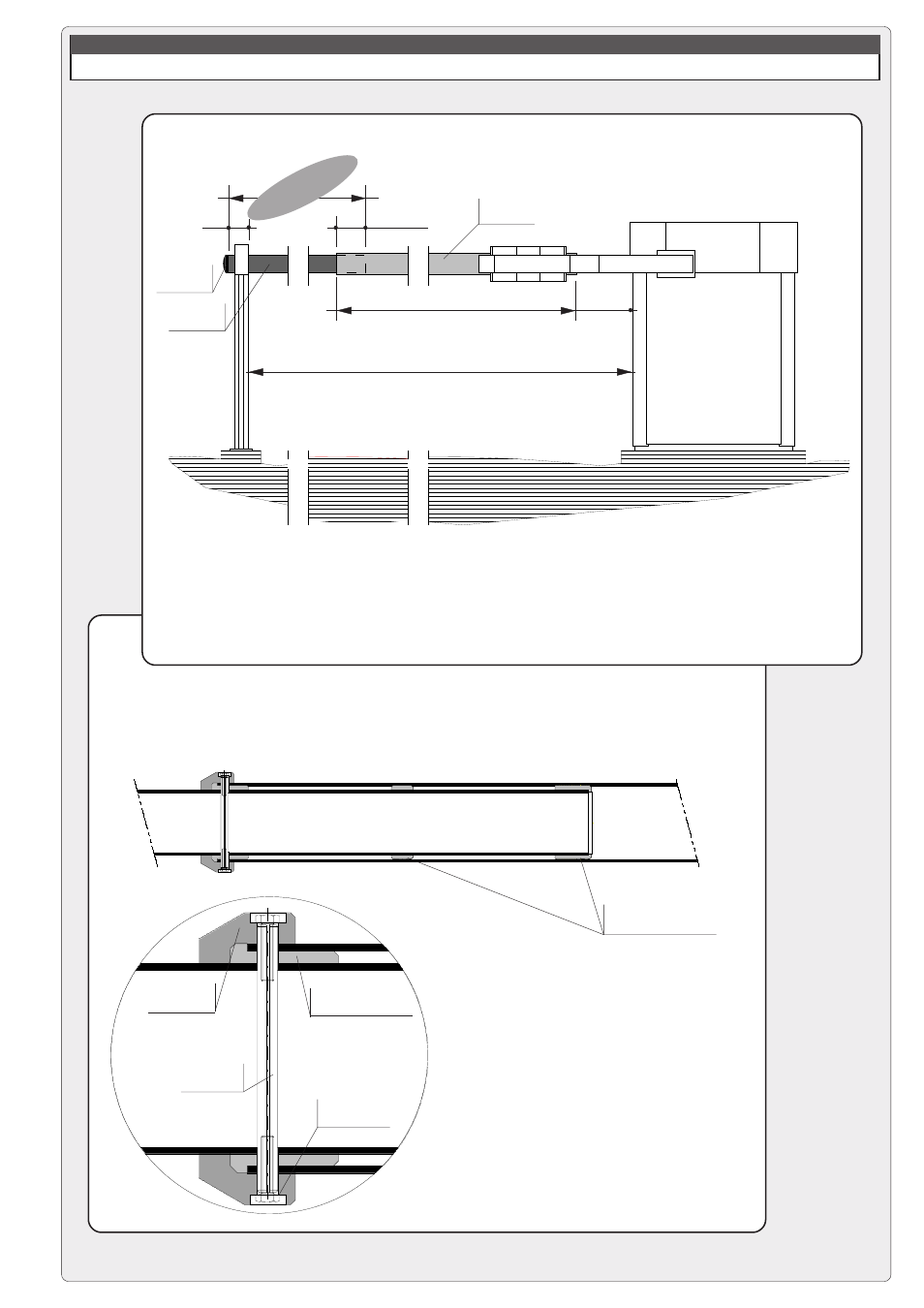
2 - PRELIMINARY ASSEMBLY OF THE BARRIER BAR
a) use the indicated formula to determine length LTP of the rear tube
(Ø100 mm), cut the tube to the correct length and install the end cap.
fixed length 6200 mm
depth of
insertion
b) assemble the barrier bar by
sliding the rear tube into the front
tube (Ø120 mm, fixed length of 6200
mm) and inserting the centring pin;
next, install and tighten the two
mounting jaws;
150
500
L
N
300
FRONT TUBE
REAR TUBE
END CAP
L
TP
= L
N
- 5850
mounting screw
on mounting jaw
mounting jaw
centring pin
thrust ring to be latched
onto the centring pin
FRONT TUBE
REAR TUBE
thrust rings already installed on
Ø100 mm rear tube
- Frog-AE (10 pages)
- Frog-A 230v (10 pages)
- Frog-A 24v (12 pages)
- Myto ME (20 pages)
- Myto-C (8 pages)
- Ferni 230v (12 pages)
- Ferni 24v (12 pages)
- F1003 Stop Arm (2 pages)
- Amico (14 pages)
- Frog-PM (18 pages)
- Frog-PC (8 pages)
- Frog-J (16 pages)
- Stylo (20 pages)
- Krono (10 pages)
- Fast (24 pages)
- Axo (18 pages)
- Axo-P324 Kit (32 pages)
- Superfrog (12 pages)
- Bx-243 (22 pages)
- BX74 - BX78 (24 pages)
- BX-P (Pratico) (18 pages)
- BX10 (34 pages)
- BX-241 (16 pages)
- BX-246 (24 pages)
- Bk (22 pages)
- Ver (24 pages)
- FrogAE-P Kit (32 pages)
- FrogAE-S Kit (32 pages)
- Ati-P Kit (36 pages)
- Ati-S Kit (36 pages)
- FerniE-P24 Kit (36 pages)
- FerniE-S24 Kit (36 pages)
- Krono-P3 Kit (32 pages)
- Axo-P3 Kit (30 pages)
- BK-12P Kit (18 pages)
- Ver U4483-B Kit (22 pages)
- Gard6S Kit (24 pages)
- Gard4S Kit (24 pages)
- Gard2S Kit (12 pages)
- G4230ST Kit (16 pages)
- G424VST Kit (16 pages)
- G6230ST Kit (16 pages)
- G624VST Kit (16 pages)
- Flex U8600 Kit (8 pages)
- Tra08 (12 pages)