CAME Gard12 User Manual
Page 3
- pag.
- pag.
- pag.
- pag.
- pag.
3
3
3
3
3
- english -
- english -
- english -
- english -
- english -
1
2
3
10
9
4
7
8
5
6
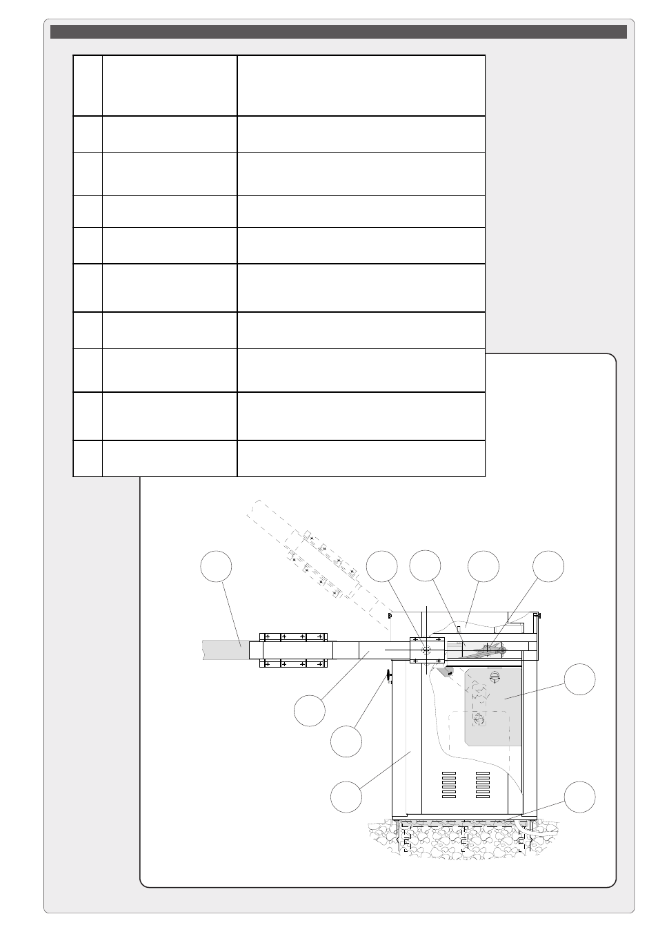
DESCRIPTION OF MAIN COMPONENTES
1
REDUCTION GEAR UNIT
24 VDC motors;
non-reversible reduction gear with die-cast aluminium
housing; uses worm gear reduction system which is
permanently lubricated with liquid grease.
2
TRANSMISSION LEVERS
In forged, galvanised steel; adjustment rods in drawn
hexagonal metal; self-lubricating joints.
3
ROTATION SHAFT
In C40 recycled steel, mounted on single-unit
supports with terminal flanges for installation of
barrier bar fork.
4
COUNTERWEIGHT
SYSTEM
Uses 25 Kg rectangular plates which are assembled
as needed.
5
RELEASE SYSTEM
Manual, with PVC handle and cord in self-lubricating
sheath; safety lock.
6
HOUSING
Load-bearing structure in steel profiles, and external
cover in press-bent 25/10 sheet steel. Both are
galvanised and painted RAL 2004 orange.
7
MOUNTING BASE
U-profile in galvanised steel, complete with anchor
stays and bolts for attachment of housing structure.
8
BARRIER BAR FORK
In galvanised steel painted RAL 9005 black; supplied
in two symmetrical parts which are ready for
assembly.
9
BARRIER BAR
In 6060 TA16 aluminium alloy painted RAL 9010
white; supplied in two circular sections (Ø120 and
Ø100 mm) which are assembled to the desired size.
10
CONTROL PANEL
Housing in ABS with IP54 level of protection,
installed in horizontal position.