2 main components, 1 dimensions, spans and anchoring holes – CAME Axo-S7 Kit User Manual
Page 3
4
3
2
1
!02%
#()5$%
4
10
1
8
5
6
7
9
11
12
13
14
16
15
17
#!-%
#!-%
2
18
19
20
21
3
(mm)
ZM3EC
ZM3C
Pa
g.
33
-
Ma
n
u
al
c
od
e:
3
1
9
U
7
5
31
9
U
7
5
ve
r.
2
.0
2.
0
0
1/
2
0
0
9 © C
A
M
E c
an
ce
lli
auto
m
ati
ci
s.p.a. -
Th
e d
ata a
n
d i
nf
or
m
ati
on r
ep
orte
d i
n th
is
in
sta
lla
tio
n m
an
u
al
a
re s
u
sc
ep
tib
le to c
h
an
g
e at a
ny ti
m
e a
n
d w
ith
ou
t o
b
lig
ati
on
o
n C
A
M
E c
an
ce
lli
auto
m
ati
ci
s.p.a. to n
otify u
se
rs.
ENGLISH
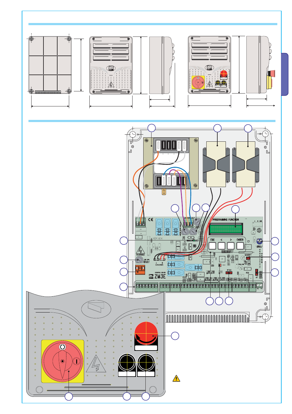
4.2 Main components
Warning! Before acting on the machinery, cut off the
main power supply and disconnect any emergency
batteries.
1 - Transformer
2 - M1 gearmotor condenser (black wires)
3 - M2 gearmotor condenser (red wires)
4 - Card fuse
5 - Accessories fuse
6 - Electrolock fuse
7 - Display
8 - Display lighting adjustment trimmer
9 - Memory roll card connector
10 - AF card connector
11 - R700 card connector
12 - Open contact error - warning LED
13 - Programming buttons
14 - Terminal board for connecting
15 - Terminal board for 230V a.c. power grid
16 - Line fuse
17 - 230V-power signalling LED
18 - STOP button
19 - CLOSE button
20 - OPEN button
21 - Safety block
{
4.1 Dimensions, spans and anchoring holes
ZM3EC