5 installation, 3 dimensions, 1 preliminary checks – CAME Frog-AE User Manual
Page 3
Before installing, do the following:
• Make sure you have a suitable omnipolar cut-off device with contacts more than 3 mm apart, and independent (sectioned off)
power supply;
• Make sure you have suitable tubing and conduits for the electrical cables to pass through and be protected against mechanical
damage;
• Fit tubing to drain away any water leaks which may cause oxidation;
• Make sure that any connections inside the case (that provide continuance to the protective circuit) be fitted with extra
insulation as compared to the other conductive parts inside;
• Make sure the structure of the gate is sturdy, the hinges work and that there is no friction between moving and non-moving
parts;
• Make sure there is a mechanical stop for opening and closing.
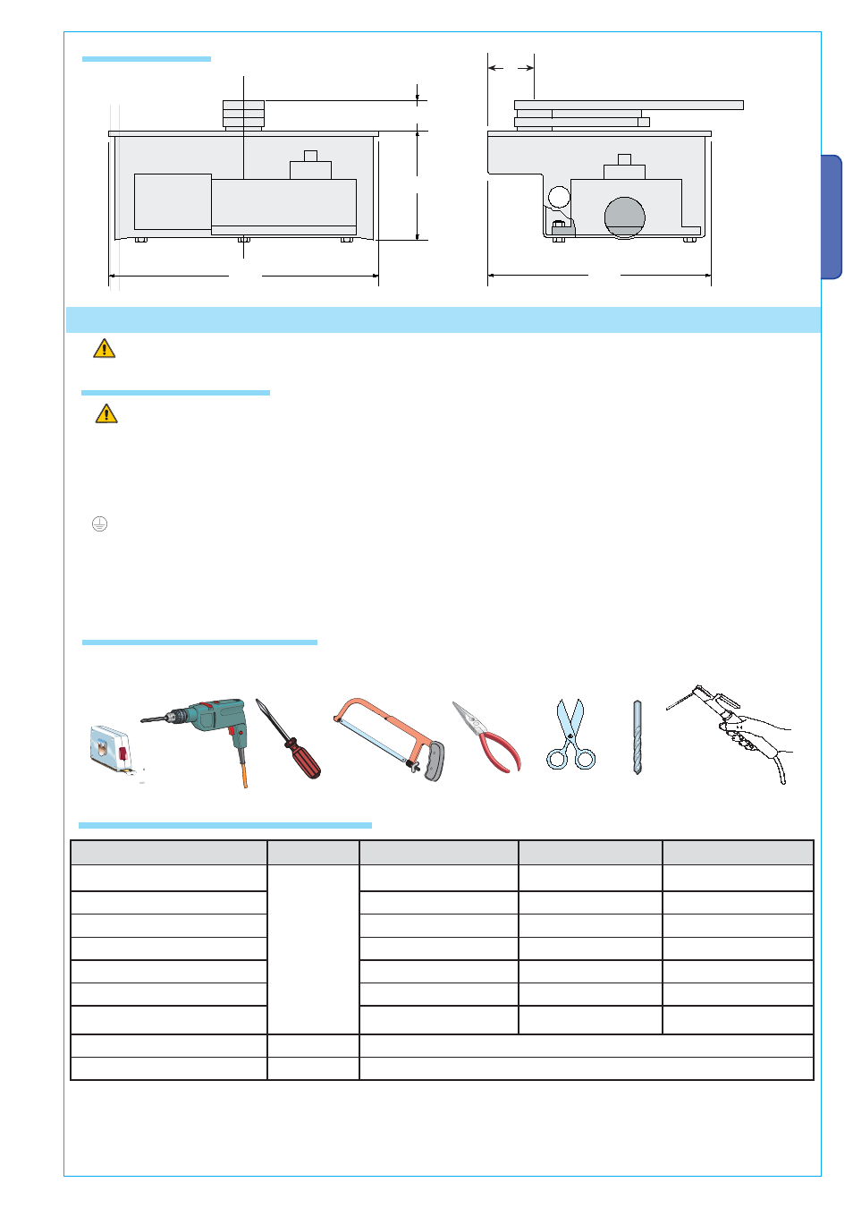
4.3 Dimensions
Make sure you have all the tools and materials you will need for the installation at hand to work in total safety and com-
pliance with the current standards and regulations. The following figure illustrates the minimum equipment needed by the
installer.
5.2 Cable and type and section
5 Installation
Installation must be carried out by expert qualified personnel and in full compliance with current regulations.
5.1 Preliminary checks
405
330
160
60
67
N.B.: If the cable length differs from that specified in the table, then you must determine the proper cable diameter in the basis of
the actual power draw by the connected devices and depending on the standards specified in CEI EN 60204-1.
For connections that require several, sequential loads, the sizes given on the table must be re-evaluated based on actual power
draw and distances. When connecting products that are not described in this manual, please refer to the instructions that come
with said products.
5.3 Cable and type and section
Connections
Type of cable Length of cable 1 < 10 m Leng. cable 10 < 20 m Leng. cable 20 < 30 m
Control panel power supply
FROR CEI
20-22
CEI EN
50267-2-1
3G x 1,5 mm
2
3G x 1,5 mm
2
3G x 2,5 mm
2
Motor power supply
4G x 1,5 mm
2
4G x 1,5 mm
2
4G x 2,5 mm
2
Flashing light
2 x 1,5 mm
2
2 x 1,5 mm
2
2 x 1,5 mm
2
Photocell transmitters
2 x 0,5 mm
2
2 x 0.5 mm
2
2 x 0,5 mm
2
Photocell receivers
4 x 0,5 mm
2
4 x 0,5 mm
2
4 x 0,5 mm
2
Accessories power supply
2 x 0,5 mm
2
2 x 0,5 mm
2
2 x 1 mm
2
Control and safety devices
2 x 0,5 mm
2
2 x 0,5 mm
2
2 x 0,5 mm
2
Encoder connection (FROG AE)
TWISTATO
3 x 0,5 mm
2
Antenna connection
RG58
max. 10 m
Pa
g.
33
-
Ma
n
u
al
c
od
e:
11
9
A
S
4
5
11
9
A
S
4
5
ve
r.
3
.
3.
33
0
6
/2
0
0
8 © C
A
M
E c
an
celli auto
mati
ci
s.p
.a. -
Th
e d
ata an
d i
nf
or
m
ati
on r
ep
orte
d i
n thi
s i
n
stall
ati
on
manu
al ar
e s
u
sc
ep
tib
le to c
h
ang
e at an
y time an
d with
ou
t o
b
lig
ati
on
o
n C
A
M
E c
an
celli auto
mati
ci
s.p
.a. to n
otify u
se
rs.
ENGLISH