2 adjusting the limit stop’s stopping zone, Fig. 8 fig. 9 – CAME Frog-A 24v User Manual
Page 7
7
T
h
e d
at
a a
n
d i
n
fo
rm
at
io
n s
h
ow
n i
n
t
h
is
d
ia
lo
g
u
e m
ay b
e c
h
an
g
ed by C
am
e C
an
ce
ll
i A
u
to
m
at
ic
i S
.p
.A
. a
t a
n
y t
im
e w
it
h
o
u
t p
ri
o
r w
ar
ning
.
ENGLISH
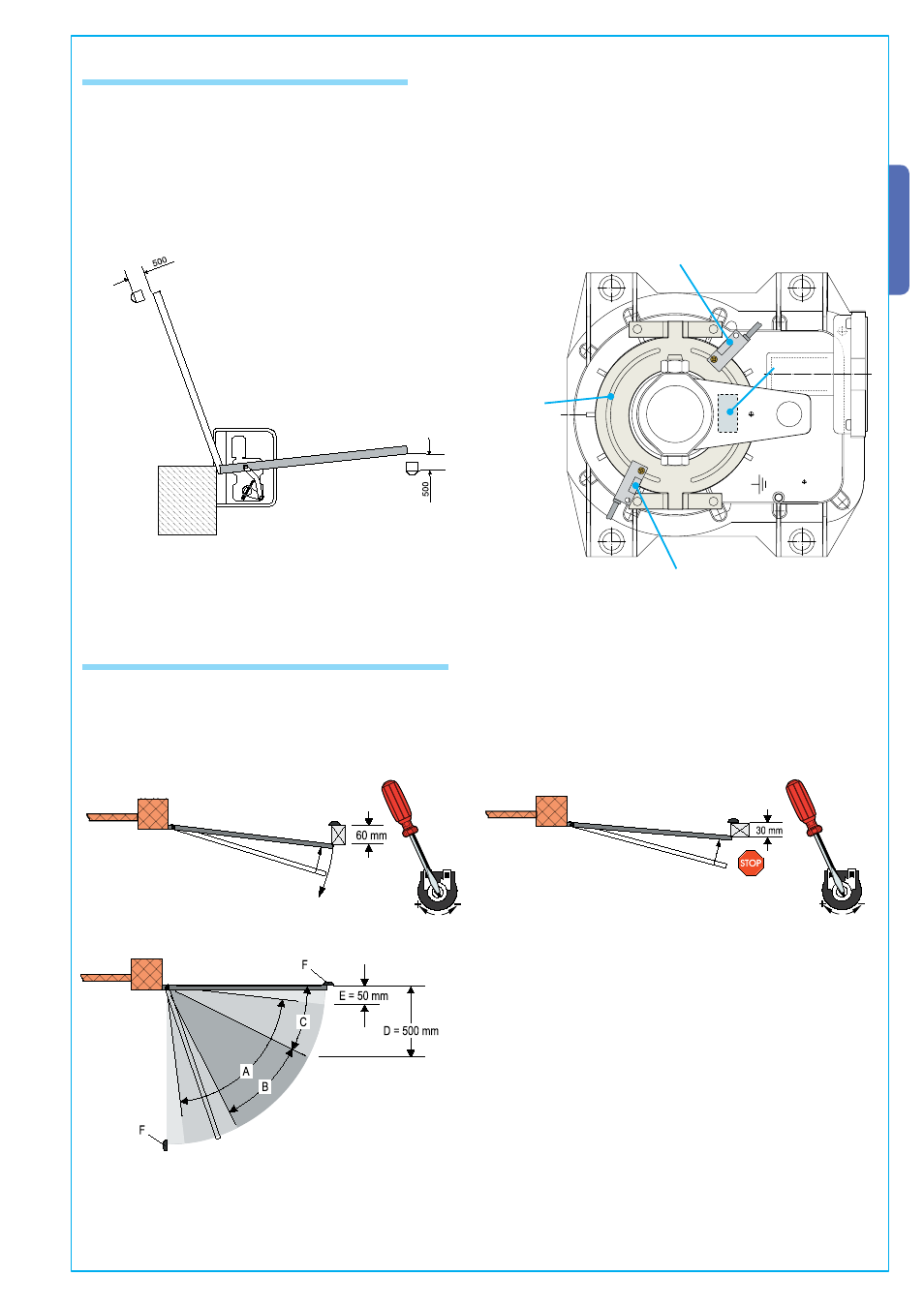
6.1 Adjusting the brake microswitches
Fig. 7
Fig. 6
– Using the motor, make so that the gate leaf is max 500mm from being fully opened.
At this point do a fi rst adjustment of the (endstop) microswitches, positioning them close to the magnet. Consider that this type of
endstop reads the magnetic fi eld. You may have to repeat the procedure to increase the precision of the adjustment (fi g. 6/7);
6.2 Adjusting the limit stop’s stopping zone
... Take the template supplied with the panel and hold it against one of the limit stops as shown in fi g. 8 (make the adjustment on
either the opening or closing limit stop).Operate the gate – using either a command button or the remote control – and rotate
the OP TIME trimmer counter-clockwise until the gate leaf inverts its direction the moment it touches the obstacle/template.
Then turn the template onto its shorter side (fi g. 9) and turn the OP TIME trimmer clockwise until the gate leaf halts touching
the obstacle/template.
Fig. 8
Fig. 9
A =Effective range of the motion-inverter amperometric sensor.
B =Run zone at normal speed.
C =Run zone at slow speed.
D =Effective range of the motion-stop amperometric sensor
E =
Opening/Closing position mechanical gate stops
Microswitch
Endstop
holding plate
Magnet
Microswitch