English 5.5 assembly diagram fig.3, 6 installing the unit, Fig.2 – CAME Frog-A 24v User Manual
Page 5: Sx dx
5
T
h
e d
at
a a
n
d i
n
fo
rm
at
io
n s
h
ow
n i
n
t
h
is
d
ia
lo
g
u
e m
ay b
e c
h
an
g
ed by C
am
e C
an
ce
ll
i A
u
to
m
at
ic
i S
.p
.A
. a
t a
n
y t
im
e w
it
h
o
u
t p
ri
o
r w
ar
ning
.
ENGLISH
5.5 Assembly diagram
Fig.3
67
67
160
100
60
3
5.6 Installing the unit
- Check the effi ciency of both moving and non-moving parts on the structure that will be supporting the operator;
- Determine, depending on the type of supporting structure and desired opening, the exact position of the motor assembly by
following the standard applications shown;
- Set up a closing end stop and an opening end stop (fi g. 4, p. 5).
- Dig, depending on the size of the assembly, a foundation pit in the chosen spot (Fig. 3);
- Prepare a drainage system in the foundation, to drain away any water leaks which may cause oxidation (fi g 3 – part.1);
- The foundation box makes for quick and easy setting up of the assembly. Place it inside the pit with the pin aligned to the upper
hinge (Fig. 3 – part. 2), sink it into the cement (Fig. 3 – part. 3) making sure it is perfectly levelled and that the upper edge is
3mm above ground level (Fig. 3 part. 4);
- Plan for the route of the electrical cables according to the command and safety instructions using the apposite hole on the box
(Fig. 3 – part. 5);
- Grease the rotation pins of the foundation box and the gate attachment lever; the hinge and pin lever must be aligned;
- Position the gate leaf between the upper hinge and the pin lever; the hinge and pin lever must be aligned;
- Secure the pin lever to the gate leaf, by welding spots 3 to 4 cm apart along the contact surface. Avoid any welding near the
threaded screws (Fig. 3 – Part. 6).
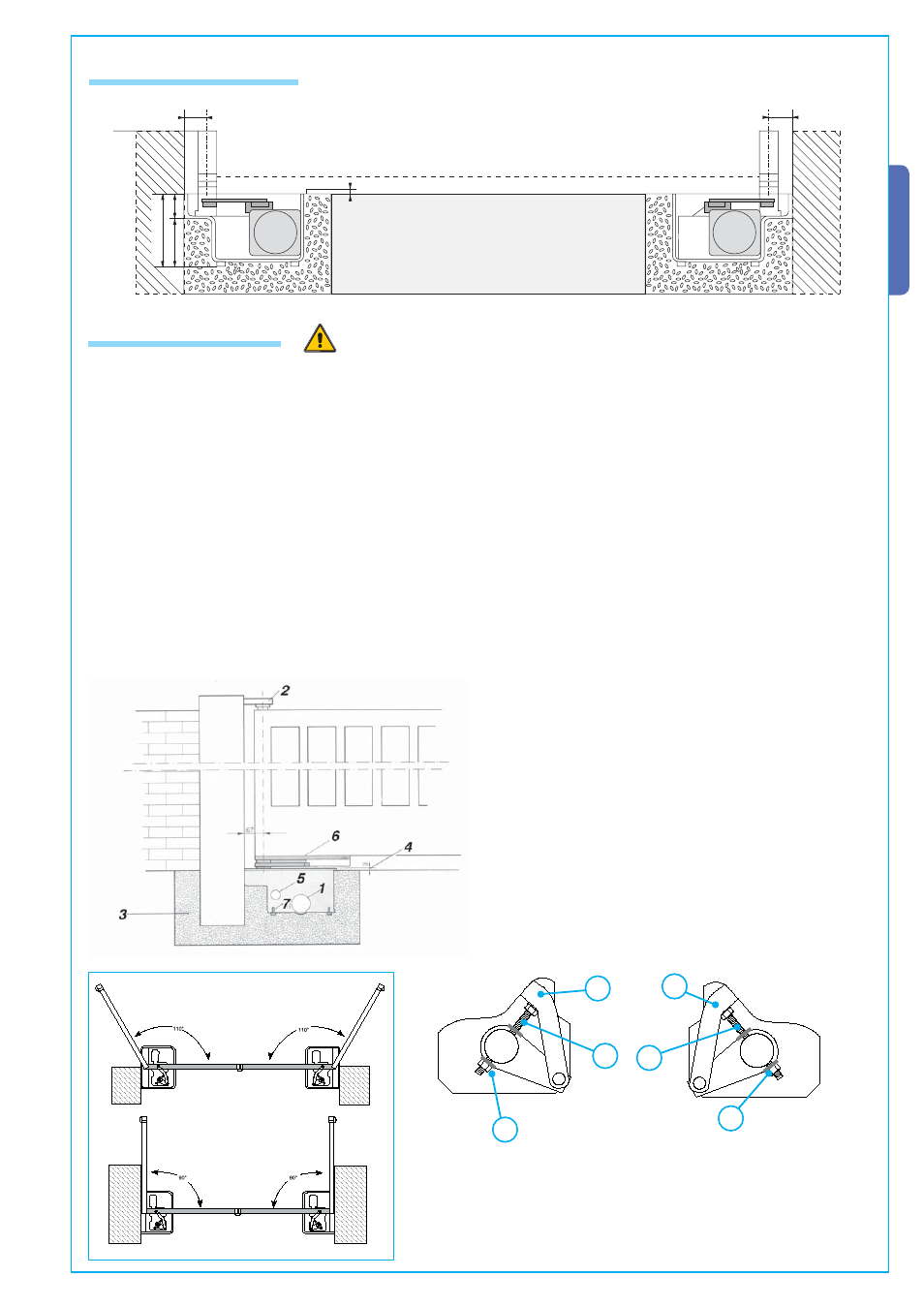
Fig.2
- Screw the M10 x 100 (A) and the M10 (B) bolt onto the gearmotor
arm as shown in fi g. 4-1 (RIGHT HAND installation) and fi g. 4-2
N(LEFT HA D installation);
- Affi x the gearmotor to the foundation box using the threaded pins
and securing it using the provided bolts and washers;
- Insert the (C ) transmission lever between the motor arm and
the box lever and electronically shut the gate against the closing
end stop.
Adjust screw (A) until it touches the (C) transmission lever.
- When testing, adjust the screw so as to allow proper closing
pressure of the gate leaf and allow its re-hooking during the
mechanism’s release procedure.
- Once adjustment is complete, secure the (B) nut.
Fig.4
DX
SX
Fig.4-1
Fig.4-2
A
B
C
C
B
A
SX
DX