Hellwig Sway Bar 55857 User Manual
Page 6
13. Drill a 15/32 (.468) hole through
BOTH walls of the frame. Make sure holes are square to one an-
other when drilling holes. It is easiest to drill through the outer wall first and use a transfer punch to
mark location on inner wall of frame.
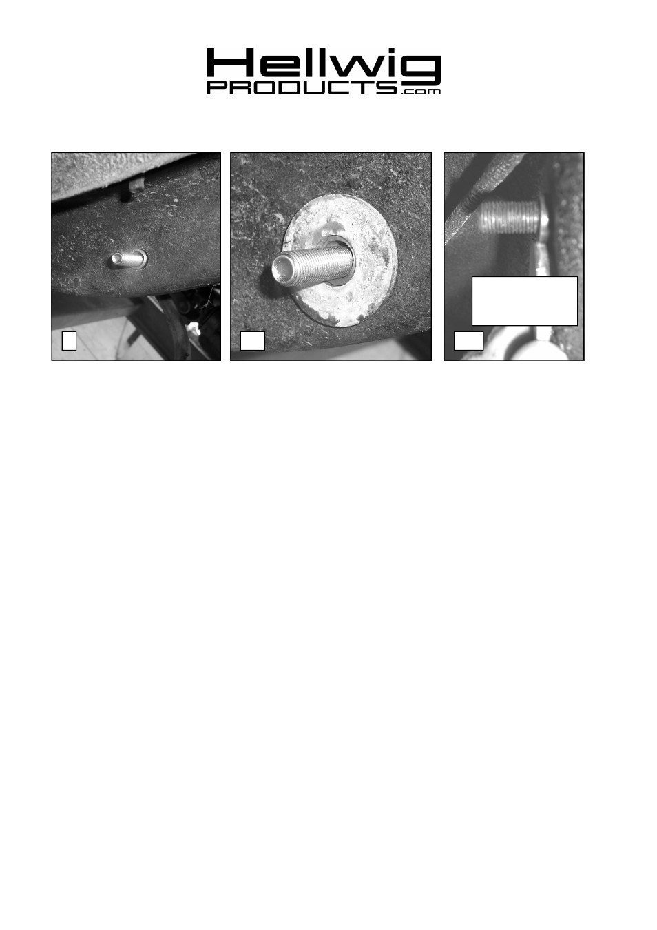
14. Drill an 11/16 (.688) hole through
OUTER wall of frame ONLY. See photo 7. A step drill works
well for this application. Do not use a hole saw as the hole must be a close fit to the spacer tube.
15. Insert 7/16 X 7” bolt through driver’s side rail as shown in PHOTO 9 with head on inside of frame
rail . Insert 7/16 X 7” bolt in same manner through passenger side rail. Insert spacer tube from out-
side of rail and check fit. The spacer tube is extra long to allow for frame section variation in the 1pc
and 2pc frames. If spacer tube is not welded to the outer wall of the frame, it must be fitted to the ve-
hicle as described in step 17.
16. For severe duty it is recommended that the spacer tube be welded to the outer frame wall. If the
spacer is to be welded, review severe service end link detail for your frame rail and skip to line 19.
IMPORTANT—
If any welding is to be done, the installer must ensure that all haz-
ards (fuel, electrical, etc) are eliminated and that fuel tanks, fuel lines, brake lines,
wiring, etc. are not affected by the welding operation.
17. Review end link detail and install Large washer over spacer tube. Check that spacer tube is at least
1/32” below the surface of large washer. Failure to do this will result in insufficient preload and
noise. Cut, file or grind end of spacer tube to achieve proper length. SEE PHOTO 10.& 10a.
18. Remove bolt and spacer from inside of frame rail.
19. Attach end link to frame as shown in detail and PHOTO 11. Applications with welded spacer do not
require the washers on the outboard wall of the frame. Torque end link bolts to 35-40 ft-lb. Due to
the variation in frame rail section width between the 1pc and 2pc frames, the bolt for the frame at-
tachment was made long enough to accommodate the widest frame section. The bolt threads can be
cut down if necessary to improve appearance of the installation.
20. Replace rear wheels and torque lug nuts to factory specification. Lower vehicle so that the full
weight of the vehicle is on the suspension.
21. Tighten axle u-bolts to 50 ft-lb.
559-734-7451 800-367-5480 FAX 559-734-7460
9
10
10a
Spacer tube must be
1/32” shorter than
edge of large washer.
5822 (R-5822)
11/08/07