Hellwig Sway Bar 55857 User Manual
Page 5
7
8
4. Place the saddle brackets onto the U-Bolts on the axle tubes. Place the U-Plates over the D shaped
bushings on the bar and attach the bar to the U-Bolts and saddle brackets with the flat washers and
nuts provided.
LEAVE LOOSE AT THIS TIME to allow for adjustment later. See PHOTO 3.
5. Position sway bar on axle so that it clears all frame mounted components including fuel tanks, brake
lines, fuel lines, etc. Sway bar can be rotated back and forth on axle to maximize clearance.
6. Assemble end links by inserting hourglass bushings and then inner sleeves into end link loops.
Fully lubricate bushings and sleeves before installation.
7. Attach end links to the center hole of the sway bar as shown in photo 2 using a 7/16-20 X 2-3/4”
bolt and washers. Align end links for best fit as shown in PHOTO 2.
IMPORTANT NOTE –
Center hole position is only for determining hole location. The end link must be moved to the
outer hole prior to initial use.
8. Due to the amount of variation in rail width on these cars, adjustment will be required to obtain best
end link alignment to the rail.
Make sure to review the appropriate frame detail for your appli-
cation. On 1 pc frames the thick washer nearest the frame can be omitted or the large spacer can be
cut down as required to obtain best fit. On 2pc frames, it may be necessary to add a thick washer be-
tween the end link and spacer.
9. The end links should be located as shown in PHOTO 2 so that the arms of the sway bar are even
with the bottom of the frame. When satisfied with location of sway bar and end links, mark hole lo-
cation for the end links on the frame.
10. Prepare to jack up vehicle by placing wheel chocks on the front wheels. After the rear of the vehi-
cle has been raised,
support frame on jack stands and remove rear wheels. Make sure end link
hole location has been marked before raising vehicle as hole location must be determined with
the full weight of the vehicle on the suspension.
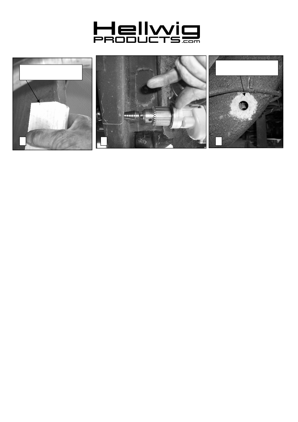
11. Transfer hole location to outer edge of frame rail. A piece of card board can be used by marking the
location of the hole on the cardboard and transferring the location to the outer rail. Drawing a line
on the frame square to the frame rails will keep the hole location square. See PHOTOS 6,7,&8.
12.
Review end link mounting detail and confirm fit before drilling holes. BEFORE DRILLING
ANY HOLES IN THE RAIL—RELOCATE AND/OR PROTECT ANY FUEL OR BRAKE
LINES THAT MAY INTERFERE WITH THE DRILL BIT OR SWAY BAR INSTALLA-
TION.
559-734-7451 800-367-5480 FAX 559-734-7460
6
Remove undercoating where
large washer contacts frame.
Mark hole location and trans-
fer to outer rail..
5822 (R-5822)
11/08/07