Gt1000 series – Brooks Instrument GT1000 User Manual
Page 7
1-1
Section 1 Introduction
Installation and Operation Manual
X-VA-GT1000-eng
Part Number: 541B078AAG
March, 2014
GT1000 Series
1-1 Description
The Brooks
®
GT1000 combines ruggedness and simplicity in design to
provide a versatile glass tube flowmeter suitable for a wide range of
applications. The GT1000 O-ring construction minimizes process downtime
by allowing for convenient in-line removal of the glass tube for cleaning and
maintenance.
1-2 Principle of Operation
The operating parts of the flowmeter consist of a tapered glass tube and a
float which operates within the tube. The fluid enters the bottom of the tube,
which has the smallest inside diameter (and smallest area), and exits from
the top, which has the largest inside diameter (and largest area). The float is
free to operate between the largest and smallest areas of the tube.
Refer to Figure 1-1.
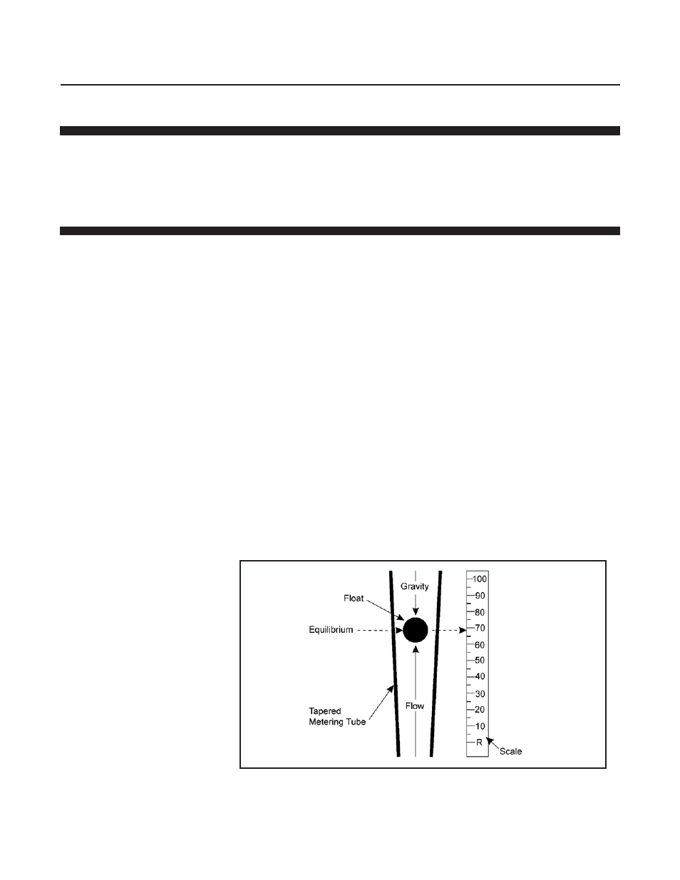
As the float moves up and down within the tapered tube, the annular area
between the float and tube varies (area increases as the float rises). This
gives the generic name of "variable area meter" for this measurement
principle. As the flow varies, the float will move within the tube until it reaches
an equilibrium position, where the tube taper creates an appropriate annular
area to balance the forces of gravity and the fluids acting on the float.
Refer to Figure 1-2.
There are four types of floats available for the GT 1000 flowmeter.
Refer to Figure 1-3.
Guide ribs are formed into the tube to keep the float operating in the center
of the tube. The guide ribs do not follow the taper of the tube. They are
parallel to the tube centerline so that the proper operating clearance for the
float is maintained for its entire range of travel. The increasing annular area
of the tube is in the area between the ribs.
Refer to Figure 1-2.
Figure 1-1 Principle of Operation