Warning, Brooks – Brooks Instrument 1100 Series User Manual
Page 22
3-2
Installation and Operation Manual
X-VA-1110-1140-eng
Part Number: 541B040AAG
September, 2012
Brooks
®
1110 and 1140 Series
Section 3 Operation
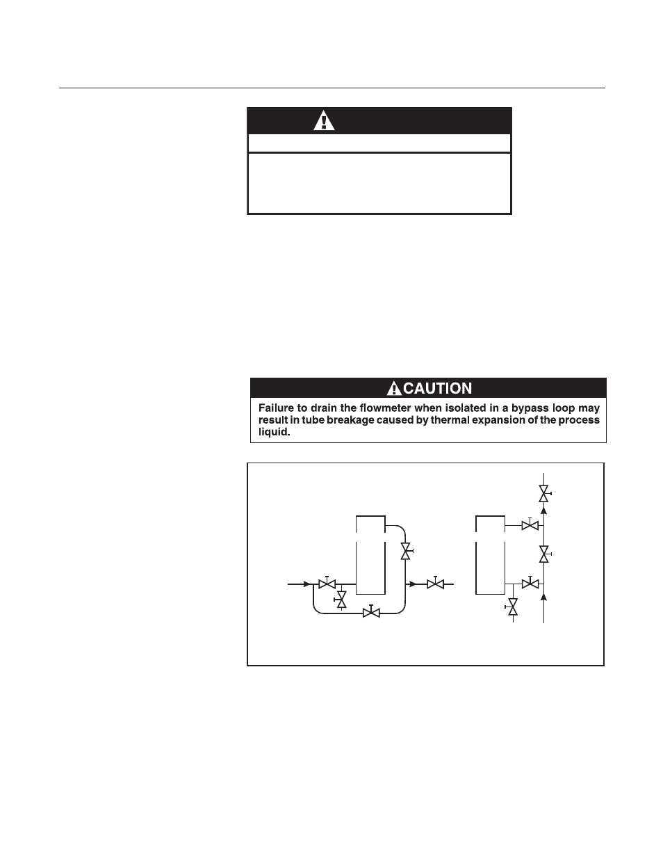
Figure 3-1 Typical Bypass Installation
A - Inlet Valve
B - Outlet Valve
C - Bypass Valve
D - Control Valve
E - Drain Valve
HORIZONTAL
LINE
D
A
E
C
VERTICAL
LINE
B
B
A
E
FLOWMETER
C
D
FLOWMETER
To initiate flow through a flowmeter using bypass piping, refer to Figure 3-1.
1. Close flowmeter isolation valves (A) and (B).
2. Fully open bypass valve (C) and slightly open control valve (D).
3. Initiate process flow. When flow has stabilized, fully open isolation valve
(B), then slowly open isolation valve (A) fully.
4. Close bypass valve (C).
5. Regulate process flow using control valve (D).
6. If meter is left in bypass configuration, open drain valve (E) to prevent
tube damage caused by thermal expansion of the process liquid.
Protective sleeve must remain over glass tube.
(Meter sizes 7 - 13 only)
Fasten meter windows securely.
Failure to comply could result in serious personal
injury or property damage.
WARNING
GLASS TUBE EXPLOSION HAZARD