Warning – Brooks Instrument MT3809E User Manual
Page 31
2-3
Models MT 3809 & 3819
Section 2 Installation
Installation and Operation Manual
X-VA-MT3809-3819
Part Number: 541B049AHG
September, 2008
2-7 Installation of Flowmeter
If the inlet and outlet valves adjacent to the indicator are to be
closed for any reason, the indicator must be completely drained.
Failure to do so may result in thermal expansion of the liquid
which can rupture the meter and cause possible personal injury.
WARNING
Recommended installation for Models MT 3809 and MT 3819 is as
follows:
a. Carefully remove the covers from each end of the flowmeter.
b. Install the flowmeter with the inlet at the bottom and the outlet at the
top.
c. When installing the flowmeter in the process line, follow accepted
plumbing practices for flanged or NPT fittings.
d. Install the flowmeter within 5° of true vertical. Use of a level is
recommended to determine the proper alignment.
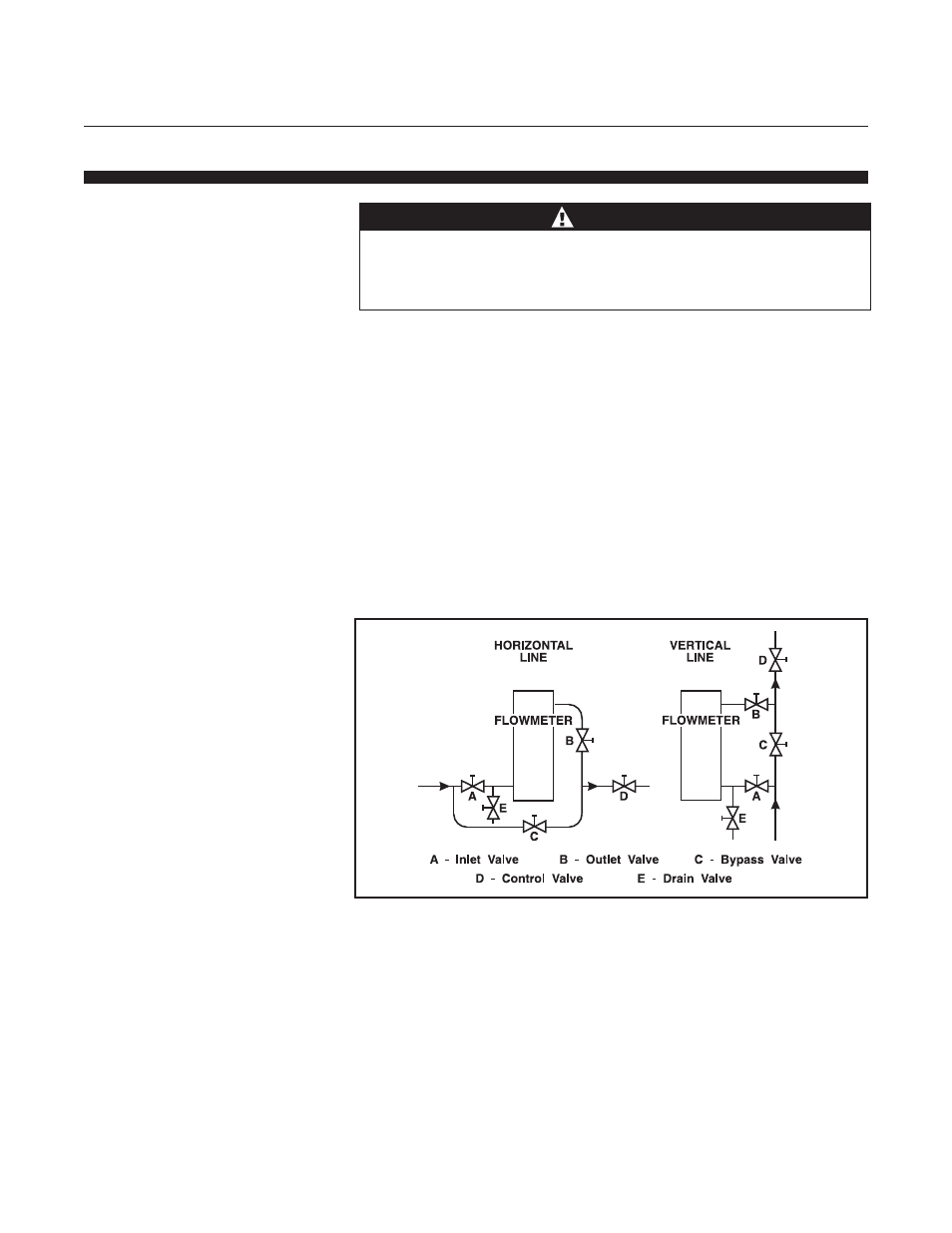
e. Installation of a bypass piping arrangement is recommended,
Figure 2-1. Bypass piping permits the meter to be isolated from the
flow line for servicing and cleaning.
Figure 2-1 Typical Bypass Installation