Brooks, Digital mfc's & mfm's – Brooks Instrument SLA5800 Series User Manual
Page 50
4-4
Brooks
®
Digital MFC's & MFM's
Section 4 Maintenance &
Troubleshooting
Installation and Operation Manual
X-TMF-SLA5800-MFC-eng
Part Number: 541B027AAG
April, 2013
4-1-2 System Checks
The Brooks Digital Series Flowmeters and Controllers are generally used
as a component in gas handling systems, which can be complex in nature.
It can therefore be very difficult to isolate a malfunction in the system. An
inaccurately diagnosed malfunction can cause many hours of unnecessary
downtime. If possible, perform the following system checks before
removing a suspect Mass Flow Meter or Controller for bench
troubleshooting or return to the factory. (especially if the system is new):
1. Verify a low resistance common connection and that the correct power
supply voltage and signals are present of the connector of the Smart
TMF.
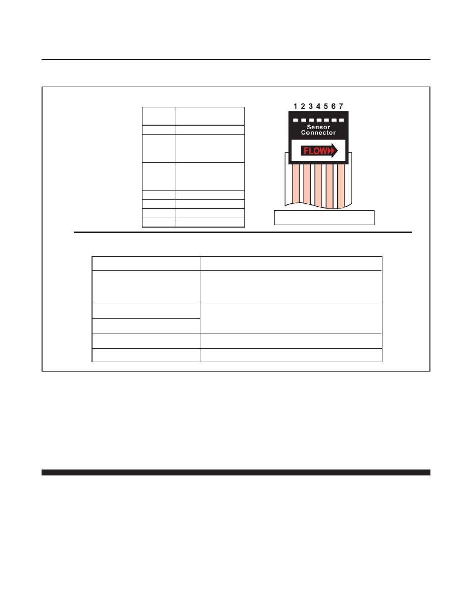
Remove the sensor connector from the PC Board for this procedure.
OHMMETER CONNECTION
RESULT IF ELECTRICALLY FUNCTIONAL
Open circuit on ohmmeter. If either heater (1) or
Pin 1 or 4 to meter body
sensor common (4) are shorted, an ohmmeter
reading will be obtained.
Pin 4 to Pin 2
Nominal 1100 ohms reading, depending on
Pin 4 to Pin 3
Pin 5 to Pin 1
Nominal 1000 ohm reading.
Pin 6 to Pin 7
Nominal 580 ohm reading.
temperature and ohmmeter current.
SENSOR
SCHEMATIC
PIN
NO.
FUNCTION
1
Heater
Upstream
2
Temperature
Sensor (Su)
Downstream
3
Temperature
Sensor (Sd)
4
Sensor Common
5
Heater Common
6
Thermistor
7
Thermistor
Table 4-1 Sensor Troubleshooting
Flex Circuit Wire Numbers