Biamp VO-4e User Manual
Page 9
9
VO-4e REAR PANEL
Failover Modes
Device-to-Device or Channel-to-Channel failover modes are supported. Only one type of failover mode can be implemented per device.
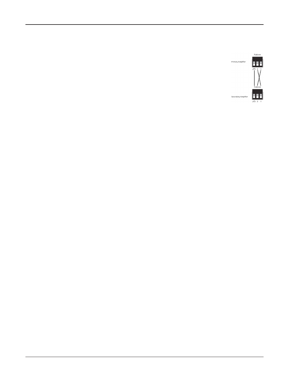
Device-to-Device Failover
VO-4e units provide for Device-to-Device failover when a fault is detected. A Failover Link Cable must be connected
between the primary and the redundant units as shown below. Connect ground to ground, and Pin 1 of the primary
device to Pin 2 of the redundant device; connect Pin 2 of the primary device to Pin 1 of the redundant device.
Failover is triggered by any of the following conditions:
• Chassis Fault
• Channel Fault
• Loss of power
• Loss of CobraNet link
• Loss of Failover Link Cable
• ELD-1 / speaker line Fault (if enabled in software)
• External amplifier Faults being asserted
Only Chassis and Channel Faults trigger the Device failover mechanism. Abnormal conditions that do not immediately impair audio will
appear as warnings but will not trigger failover.
After a failover condition has been asserted, a power cycle of the units is required to recover from the failover. This can be done either by
physically repowering the devices or by performing a ‘Device Reset’ in the Vocia software via the Test tab of the device dialog. The units
are required to be reset within 10 seconds of each other in order to ensure the primary device resumes control.
Channel-to-Channel Failover
Channel-to-Channel failover is supported as 1:1 Channel. In this configuration, channel pairs can be specified and adjacent channels will
act as a redundant backup. Channel 2 will act as backup for Channel 1 and Channel 4 will act as backup for Channel 3.
Channel failover is triggered by either a Channel Failure Fault, an ELD-1/Speaker Line Fault (if enabled in software) or an amplifier Fault
Input being asserted.
The VO-4e will return to normal operation after the Fault condition is cleared and the unit is re-powered or reset via the Test tab in the
Properties sheet.