Biamp VO-4e User Manual
Page 8
8
VO-4e REAR PANEL
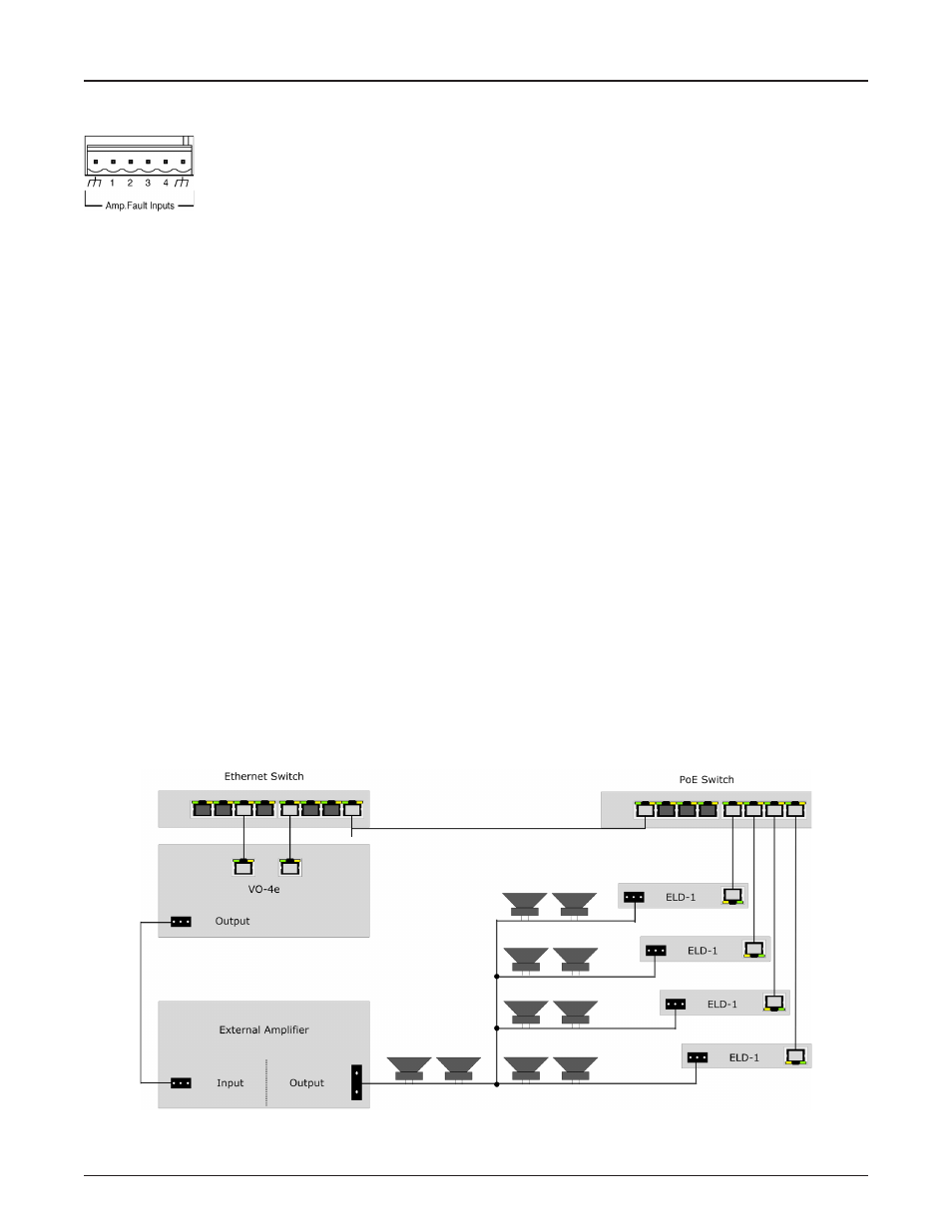
Amp Fault Imputs
Four amplifier Fault Inputs are provided via a six-way 0.2” (5.08mm) pluggable screw terminal block. These allow
for fault monitoring of the output of the VO-4e as indicated from an external amplifier. By default each input allows
an external voltage-free contact closure to ground to indicate a fault condition for the corresponding VO-4e Output
channel. Inputs are pulled high internally to create a default non-asserted condition. When configured for device
failover the Amp Fault Input connections must be paralleled between the main and failover device. This is software configurable so if
inverse operation is required this can be adjusted per input.
Output Fault Detection (VO-4e output channel used in conjunction with a Vocia End of Line Device 1 [ELD-1])
The VO-4e monitors audio output circuit integrity per channel by monitoring multiple out-of-band (inaudible), high frequency tones in
conjunction with ELD-1 devices that have been assigned to the relevant channel using the Vocia software. To prevent the possibility of
interference with these monitored tones:
• Recorded audio messages or audio content with continuous or swept tonal components (e.g., alert tones) should be band limited at
15 kHz during recording;
• Program signal levels should be adjusted to minimize clipping, as severely clipped signals may also affect these out-of-band fault
detection tones.
• The use of shielded speaker cable is not supported;
• Highly capacitive speaker lines or loads may prevent correct operation of the ELD detection system;
• Legacy monitored speaker circuits that use capacitors and resistors or similar methods must have all legacy monitoring circuitry
removed for correct operation of the ELD detection system;
• If legacy speaker systems and speaker wiring are to be re-used, these must conform with the requirements herein;
• Any external power amplifier equipment must be capable of relaying the out-of-band fault detection tones to the ELD-1. For reliable-
performance a frequency response of better than -3dB at 24kHz must be supported through the amplifier and all speaker wiring up to
the End of Speaker Line connections on the ELD-1s;
• The amplifier gain or level control must be set so that nominal output level from the VO-4e (-10dBu, 0dBu or +4dBu; as set in Vocia
software) delivers an output level from the amplifier 6dB below the amplifier maximum output level (clip level). This setting must be
accurate and must remain constant for predictable operation of ELD-1 units.