Biamp VO-4e User Manual
Page 6
6
VO-4e REAR PANEL
Connections
All numbered audio, relay and power connectors on the rear panel of the unit are configured with the lowest output or input on the left of
the connector as viewed from the rear of the unit.
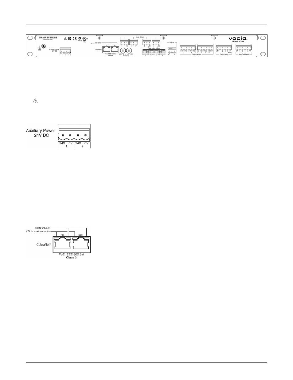
Auxiliary Power
Dual 24V DC power inputs are provided on a four-way 0.2” (5.08mm) pluggable screw terminal
block. Monitoring of the supply input is software configurable. If 24V DC is not supplied to a
monitored input, a loss-of-supply fault will be reported. If no Auxiliary Power monitoring is required
the option must be deselected in the Vocia software to prevent an Auxiliary Supply Fault being
reported. A Loss of Supply Fault is indicated via the Vocia software and by a blinking yellow
‘Chassis Fault’ indicator on the front panel. Auxiliary power supplies must meet the voltage range and power requirements detailed in the
following specification table. Local standards, norms or codes may require the use of certified power supplies and may require observance
of minimum ‘on battery’ running times both for standby and maximum power conditions. If used, dual 24V redundant power supplies must
each independently meet the total power requirements of the unit.
The pluggable screw terminal connectors provided will accommodate wire sizes from 12-18 AWG. External over-current protection must be
provided, according to the current carrying capacity of the connecting wires. The Auxiliary power inputs must not be connected to Chassis
or ground. The Auxiliary power must be floating with respect to ground.
Network Connections
The VO-4e is a CobraNet device. A Primary and Secondary CobraNet connection is provided for
this. These connections support powering via 802.3af or 802.3at (type 1) PoE switches or external
PoE Supplies. Monitoring of the PoE supply input is software configurable. If PoE power is not
supplied to a monitored input, a loss-of-supply fault will be reported. If no PoE Power monitoring is
required the option must be deselected in the Vocia software to prevent a PoE Supply Fault error
being reported. A Loss of Supply Fault is indicated via the Vocia software and by a flashing yellow
‘Chassis Fault’ indicator on the front panel. All CobraNet routing and bundle assignments are processed by the Vocia devices locally.
Vocia makes dynamic use of available bundles in CobraNet. A 100Base-T Ethernet switch (not repeater hub) is required when networking
multiple units. CobraNet utilizes standard CAT5, CAT5e, CAT6, or CAT7 cabling, which has a specified maximum length of 328 feet (100
meters). Additional Ethernet switches, or switches which provide fiber-optic interface, can be used to extend the physical distance between
units within a network. Please note that CobraNet limits network extensions to seven hops (one-way transmissions) within a network. The
CobraNet network connection is configured with the Primary connector on the left and the Secondary (redundant) connector on the right.
The Primary and Secondary CobraNet ports are provided to facilitate connection redundancy. Each connector provides two LEDs that
indicate Ethernet link and network activity.
Caution - Due to potential energy hazard, connections to the Auxiliary Power 24V DC
inputs must be made by a qualified electrician or other qualified person as
required to conform with all local codes .