Biamp VO-4e User Manual
Page 7
7
VO-4e REAR PANEL
CobraNet LED indication
Left LED
Right LED
Description
None
None
No Data Connectivity or CobraNet activity
None
Flashing green
Network Link established. Typically seen on Secondary port when acting as a failover to the
Primary connection.
Yellow
Flashing green
Network Link established. Typically seen on Secondary port when acting as a failover to the
Primary connection.
Flashing yellow
Flashing green
Network Link established and CobraNet activity detected; The unit is acting as a CobraNet
Conductor
Flashing yellow
None
CobraNet fault. Check cabling and configuration for errors
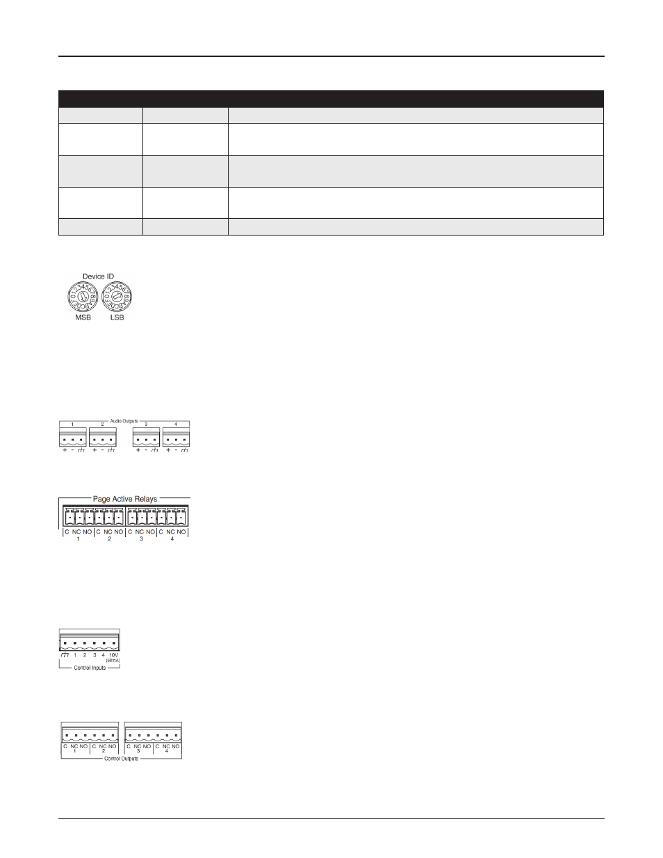
Device ID switches
The rotary ID switches are located on the back of the unit and are used to provide a unique Device ID. The switches
are in hexadecimal format. All Vocia units of the same type must have a unique Device ID to function properly within
a Vocia Paging World (for instance, it is not possible to have two Vocia Devices of the same type with the same
Device ID of hex 07).
As an example, to assign a Device ID of hex 07, leave the MSB switch on 0, turn the LSB switch to 7. To create an ID of hex B7, turn the
MSB switch on B, and turn the LSB switch to 7. Device ID switches should be set using a 0.1 inch (2.5mm) to 0.12 inch (3.0mm) flat blade
screwdriver. More information on setting IDs and the hexadecimal numbering scheme used can be found in the Vocia Software Help File.
Analog Audio Outputs
Four 0.2” (5.08mm) three way pluggable barrier strip connectors are provided for analogue audio
signal output. The Vocia software enables a nominal output level of -10dBu, 0dBu or +4dBu to support
a wide range of connection devices.
Page Active Relays
Page Active Relays (PAR) are provided in the form of one Form C (single pole, changeover) relay
presented per output channel. Each PAR connector is a six way 3.5mm pluggable barrier strip
connector. The Page Active relay connections are labeled as follows:
• C – Relay Common
• NC – Normally Closed
• NO – Normally Open
Control Inputs
Four separate Control Inputs are provided via a six-way 0.2” (5.08mm) pluggable screw terminal block. Each Control
Input allows for an external voltage-free contact closure to ground to assert a Control Input Event as configured in Vocia
software. In addition to the four control inputs, a ground and 10V reference Out (100mA) is provided. When configured
for device failover the Control Input connections must be paralleled between the main and failover device.
Control Outputs
Four Control Outputs are provided via two six-way 0.2” (5.08mm) pluggable screw terminal blocks. Each
Output has a Common, Normally Closed (NC) and a Normally Open (NO) connection. Outputs will be
capable of being associated with control Output Events configured in Vocia software. Both NC and NO
connections are able to be used at the same time. When configured in a Failover Mode the Controls outputs are able to be used to indicate
the active state of the respective output channel. When configured for device failover as NO and NC relay connections are being used,
consideration should be given to the performance of the circuit before and after failover.