Biamp VO-4e User Manual
Page 5
5
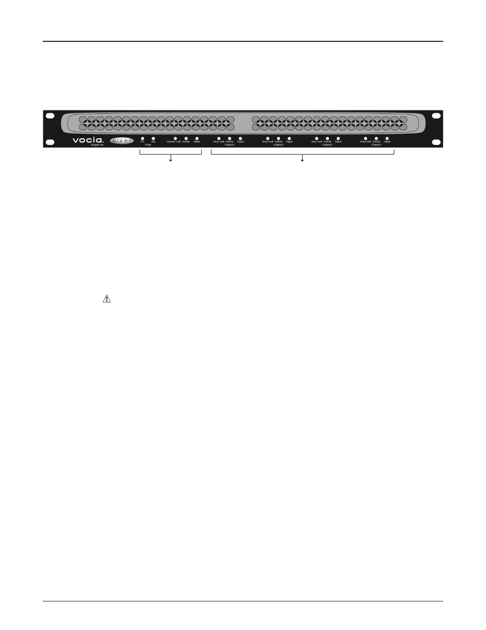
VO-4e FRONT PANEL
Setup and Use
The Vocia software provides the interface for configuring and programming the VO-4e. The information supplied by this manual relates to
hardware installation, physical connections, device and channel failover concerns. For more details on software setup, please consult the
Vocia Software Help File.
System Indicators
The LED indicators on the front panel provide information and operational status of the unit and associated output channels. LEDs have
been grouped into Chassis and Channel indicators.
Chassis Indicators
These indicators relate to the entire unit (chassis).
PoE is a green LED indicator that will illuminate when PoE power is applied to the unit via either or both CobraNet ports.
Aux is a green LED indicator that will illuminate when an auxiliary DC supply is applied to the unit via either or both 24V Auxiliary power inputs.
Chassis Fault is a yellow LED indicator that illuminates when a Chassis Fault has occurred. There are two types of Chassis Faults that
can be reported depending on the severity of the problem. Flashing yellow indicates a Warning that means some aspect of the unit is not
performing within normal specification. Audio may still be passing but if the condition causing the warning is not corrected chassis failure
may occur. Solid yellow indicates a fault which means that some aspect of the unit has failed and audio may no longer be passing through
the device. Use Vocia software to determine the specific type of chassis warning or Fault that has occurred.
Activity is a two-color LED that indicates the configuration status of the device. A solid green LED indicates that the unit is configured.
A flashing yellow LED indicates the unit is active but unconfigured. A solid yellow LED indicates the unit is configured and in standby.
Standby only occurs when a unit has been designated as a redundant device when Device Failover is enabled.
Status is a tri-color LED that indicates the health of the hardware. A green LED indicates that the unit powered up normally. A flashing
yellow LED is shown briefly during the power-up self-test and will turn solid green upon successful start. A red LED indicates that the unit
experienced a problem during the power-up self-test.
Channel Indicators
These indicators relate to each of the four channels.
Amp Fault is a yellow LED that illuminates when the corresponding Amp Fault Input on the rear of the unit has been asserted.
Activity is a two-color LED that illuminates green when that channel is configured and actively passing audio and yellow when that channel is
configured and in standby. Standby only occurs when a channel has been designated as redundant channel in a failover configuration.
Signal is a tri-color LED that that indicates audio signal presence on the amplifier channel. Green indicates that the audio signal level is between
-48 dBFS and -18 dBFS, yellow indicates a signal level between -18 dBFS and -2 dBFS, and red indicates clipping (above -2dBFS).
Refer to the caution in the Rear Panel Auxiliary Power section .
Chassis Indicators
Channel Indicators