Example configuration – Biamp AudiaVOIP User Manual
Page 6
6
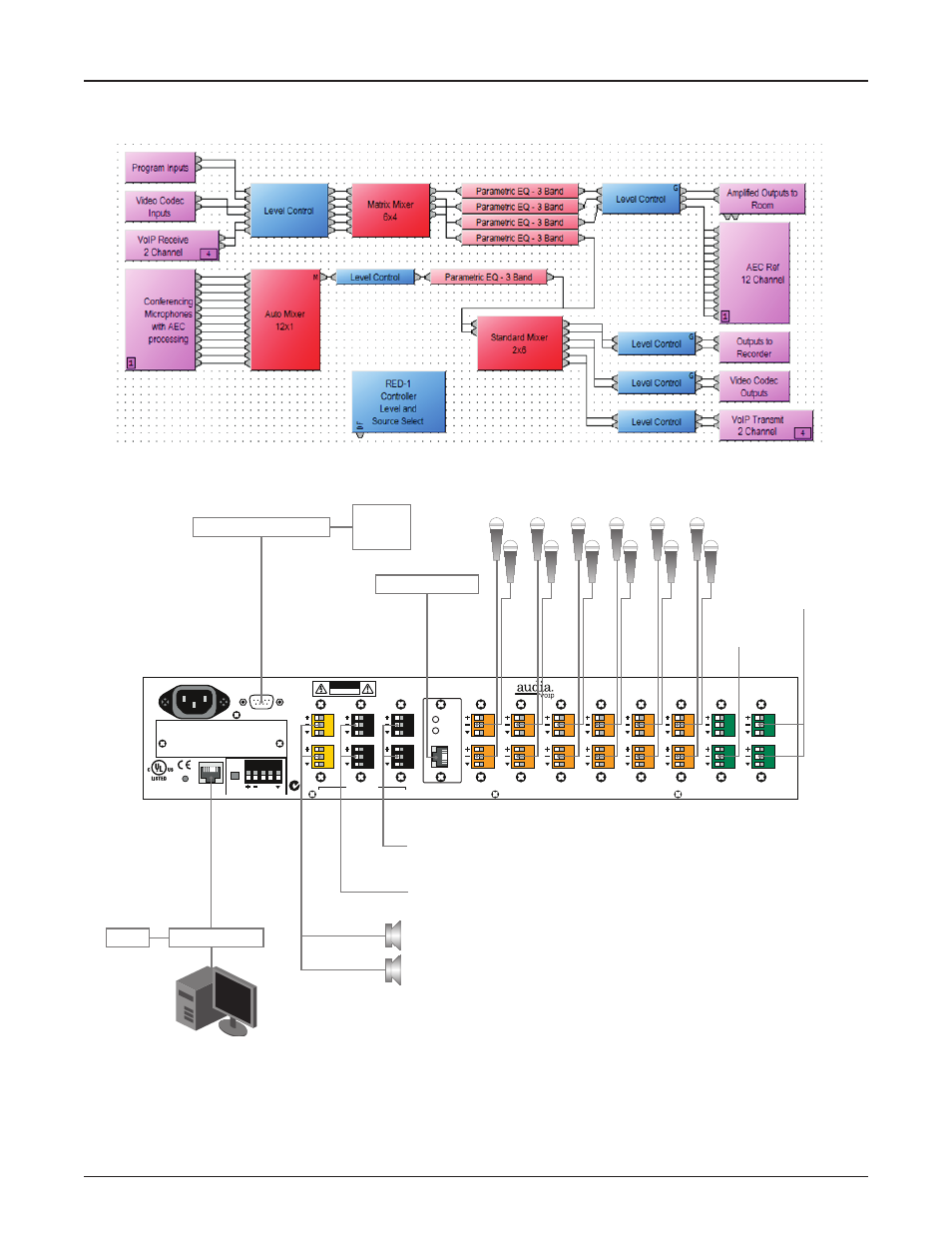
EXAMPLE CONFIGURATION
Serial Control Port
100-240V
~
50/60Hz
150 Watts
CobraNet
®
connections only
secondary
U.S. pat. no. 4,922,536
primary
link
Remote Control Bus
class 2 wiring
BLACK connectors = OUTPUTS
YELLOW connectors = AMP OUTPUTS
GREEN connectors = INPUTS
24VDC
1.5A
term
hi lo
Ethernet
CAUTION
RISK OF ELECTRICAL SHOCK.
DO NOT OPEN.
In 1
In 2
Out 23
Out 24
In 3
In 4
Out 21
Out 22
In 5
In 6
Out 19
Out 20
In 7
In 8
Out 17
Out 18
In 9
In 10
Out 15
Out 16
In 11
In 12
Out 13
Out 14
In 13
In 14
Out 11
Out 12
In 15
In 16
Out 9
Out 10
In 17
In 18
Out 7
Out 8
In 19
In 20
Out 5
Out 6
In 21
In 22
Out 3
Out 4
ORANGE connectors = AEC INPUTS
link / activity
in use / conductor
LEDs
52SJ
N24138
BIAMP SYSTEMS
Made in USA, US and Imported Parts
www.biamp.com
Model: Audia
link/act
VoIP
full
duplex
• Can receive control
information (controlling
dialer, room levels, etc.)
• Send serial strings to other
devices (control lighting and
camera systems, etc.)
2 VoIP extensions for
internal and external
telephone conferencing
(Sona AEC processing
removes all echo from
audio delivered to callers)
Two 30W speaker circuits.
Direct drive 4, 6, or 8Ω speakers
or 70/100V distributed circuits
(external transformers required)
Audio outputs to recorders,
external amplifiers, etc.
Audio outputs to video codecs
(Sona AEC Processing removes all echo
from audio delivered to far end)
Audio inputs from
video codecs
Presentation audio
sources (PC, DVD,
Projector Audio)
Third Party Control System
Control Network
RED-1
VoIP Network
Graphical
User
Controls
• Audia DSP programming
interface
• Interface to external
control systems
• Interface to Biamp
controllers, daVinci, RED-1
or iPad Dialer App
Serial Port for interface to external
control systems:
Ethernet Control Interface