Audiavoip rear panel – Biamp AudiaVOIP User Manual
Page 5
5
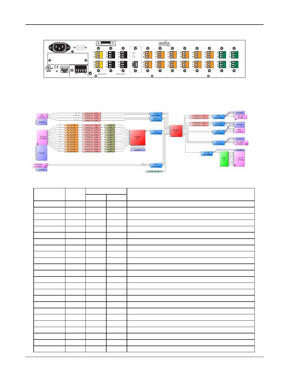
AudiaVOIP REAR PANEL
AudiaVOIP
AudiaVOIP comes preconfigured with 4 mic/line inputs, 12 AEC inputs, 4 line outputs, 2 amplified outputs
and 2 VoIP lines. The device comes preloaded with a default software configuration file that is able to be
customized to meet a wide range of applications.
Preloaded DAP File
Serial Control Port
100-240V
~
50/60Hz
150 Watts
CobraNet
®
connections only
secondary
U.S. pat. no. 4,922,536
primary
link
Remote Control Bus
class 2 wiring
BLACK connectors = OUTPUTS
YELLOW connectors = AMP OUTPUTS
GREEN connectors = INPUTS
24VDC
1.5A
term
hi lo
Ethernet
CAUTION
RISK OF ELECTRICAL SHOCK.
DO NOT OPEN.
In 1
In 2
Out 23
Out 24
In 3
In 4
Out 21
Out 22
In 5
In 6
Out 19
Out 20
In 7
In 8
Out 17
Out 18
In 9
In 10
Out 15
Out 16
In 11
In 12
Out 13
Out 14
In 13
In 14
Out 11
Out 12
In 15
In 16
Out 9
Out 10
In 17
In 18
Out 7
Out 8
In 19
In 20
Out 5
Out 6
In 21
In 22
Out 3
Out 4
ORANGE connectors = AEC INPUTS
link / activity
in use / conductor
LEDs
52SJ
N24138
BIAMP SYSTEMS
Made in USA, US and Imported Parts
www.biamp.com
Model: Audia
link/act
VoIP
full
duplex
Card Configuration
The fixed configuration is achieved with the following cards:
Card
Slot
Channel
Default Software Configuration file connection
Input
Output
IP-2
1
1
Program Left
2
Program Right
IP-2
2
3
Codec Receive Left
4
Codec Receive Right
AEC-2HD
3
5
Room Microphone 1
6
Room Microphone 2
AEC-2HD
4
7
Room Microphone 3
8
Room Microphone 4
AEC-2HD
5
9
Room Microphone 5
10
Room Microphone 6
AEC-2HD
6
11
Room Microphone 7
12
Room Microphone 8
AEC-2HD
7
13
Room Microphone 9
14
Room Microphone 10
AEC-2HD
8
15
Room Microphone 11
16
Room Microphone 12
VoIP-2
9
17
17
VoIP Telephone Line 1
18
18
VoIP Telephone Line 2
OP-2e
10
19
Codec Transmit Left
20
Codec Transmit Right
OP-2e
11
21
Auxiliary Output A
22
Auxiliary Output B
PA-2
12
23
4 or 8 Ω Room Speakers Channel 1
24
4 or 8 Ω Room Speakers Channel 2