Maintenance – Flowline AXXX Smart Trak User Manual
Page 8
Step Eleven
MAINTENANCE
Step Twelve
MAINTENANCE
General:
The Smart Trak™ with Compact Junction Box requires no periodic
maintenance except cleaning as required. It is the responsibility of
the user to determine the appropriate maintenance schedule, based on
the specific characteristics of the application liquids.
Cleaning Procedure:
1. Power:
Make Sure that all power to the sensor, controller and/or
power supply is completely disconnected.
2. Sensor Removal:
Make sure that the tank is in a state where it
is safe to remove the sensors. Carefully, remove the Smart Trak™
from the installation.
3. Cleaning the Sensor:
Use a soft bristle brush and mild deter-
gent, carefully wash the Smart Trak™. Do not use harsh abra-
sives such as steel wool or sandpaper, which might damage the
surface sensor. Do not use incompatible solvents which may
damage the sensor's PP or Ryton plastic body.
4. Sensor Installation:
Follow the appropriate steps of installa-
tion as outlined in the installation section of this manual.
Testing the installation:
1. Power:
Turn on power to the switches and/or power supply.
2. Immersing the switch:
Immerse the sensing tip of each switch
in its application liquid, by filling the tank up to the switches point
of actuation. An alternate method of immersing the switch during
preliminary testing is to hold a cup filled with application liquid
up to the switch's tip.
3. Test:
With the switch being fluctuated between wet and dry
states, the switch will open or close depending on wiring status.
If the system doesn't have an input indicator, use a voltmeter or
ammeter to ensure that the switch produces the correct signal.
4. Point of actuation:
Observe the point at which the rising or
falling fluid level causes the switch to change state, and adjust the
installation of the switch if necessary.
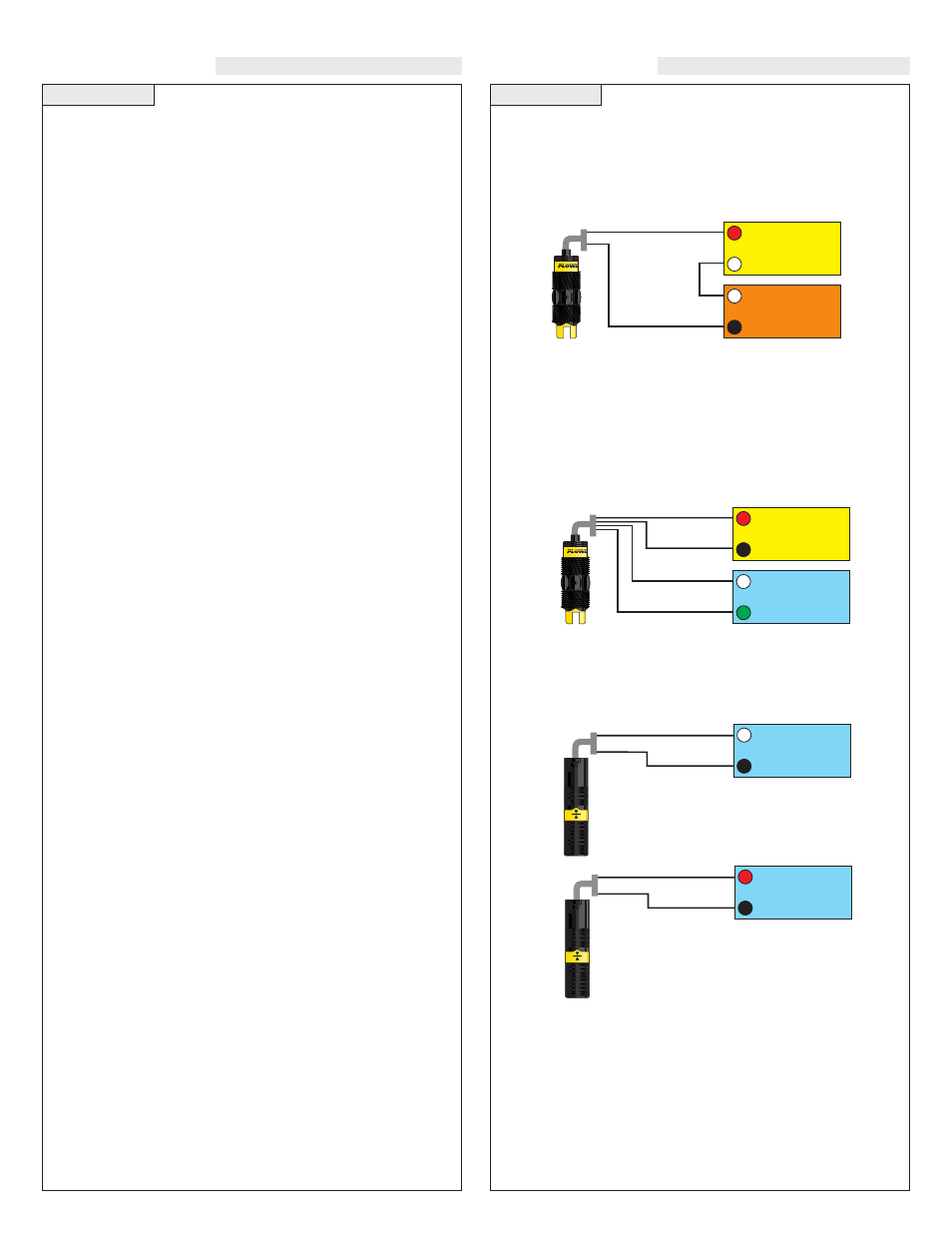
Current Test (Ultrasonic and Vibration only):
Used to verify if the sensor is indicating a wet or dry condition. This
test uses only two wires (Red and Black). The sensor draws 5 mA
(ultrasonic) or 8 mA (vibration) when it is dry, and 19 mA when wet.
The White and Green wires are not used.
Red
Black
24 VDC
Power Supply
+
-
Multimeter
(Continuity)
-
+
White
Green
Red
24 VDC
Power Supply
+
-
Multimeter
(mA)
-
+
Black
Normally Open Wiring:
Relay Contact Test (Ultrasonic and Vibration only):
Used to verify if the relay contact is switching between dry (open) and
wet (closed). Test requires Red wired to Positive (+) and Black wired
to Negative (-) on a 12 to 36 VDC power supply. Check for continu-
ity across Green and White (open for dry and closed for wet).
Reversing Red and Black wires will result in a closed when dry and
open when wet condition.
Contact Test (Buoyancy only):
Used to verify if the reed switch is switching between dry (open) and
wet (closed). Check for continuity across Black and White (open for
dry and closed for wet). Checking across Black and Red will result
in a closed when dry and open when wet condition.
White
Black
Multimeter
(Continuity)
-
+
Normally Open
(Dry)
Red
Black
Multimeter
(Continuity)
-
+
Normally Closed
(Dry)