Assembly of smart trak, Safety precautions – Flowline AXXX Smart Trak User Manual
Page 4
Step Four
ASSEMBLY OF SMART TRAK™
Step Three
SAFETY PRECAUTIONS
About this Manual:
PLEASE READ THE ENTIRE MANU-
AL PRIOR TO INSTALLING OR USING THIS PRODUCT. This
manual includes information on the Smart Trak™ with Compact
Junction Box: AU_5-434_, AZ_8-434_ and AV_6-343_. The units
are identical except for the number of switch points and the sensors
technology.
User's Responsibility for Safety:
Flowline manufactures
a wide range of liquid level sensors, controllers, and mounting sys-
tems. It is the user's responsibility to select components that are
appropriate for the application, install them properly, perform tests
of the installed system, and maintain all components. The failure to
do so could result in property damage or serious injury.
Proper Installation and Handling:
Use a proper sealant
with all installations. Never overtighten the components. Always
check for leaks prior to system start-up.
Material Compatibility:
Glass filled Polypropylene (PP, a polyolefin): Track, end cap, wire
retainer clips, bayonet adapter, level switch and sensor car for all
Smart Trak Assemblies.
Polychlorotrifluoroethylene (PCTFE, a fluoroplastic): Sensor car
locking bolt and screw.
Polypropylene (PP, a polyolefin): Sensor, top compression fitting,
thrust plate, locking pin and 2" NPT fitting.
Viton (a fluorocarbon): O-ring.
Neoprene (w/silicon gel for lubrication): Wire gasket.
Santoprene (w/silicon gel for lubrication): Seal plug.
Make sure that the application liquids are compatible with the
materials that will be wetted. To determine the chemical compati-
bility between the components and its application liquids, refer to
the Compass Corrosion Guide, available from Compass
Publications (phone 858-589-9636).
Temperature and Pressure:
Smart Trak™ is designed for
use in application temperatures up to 90° C (194° F). It is not
designed for pressurized applications due to the wiring that must
travel through a gasket at the head.
Wiring and Electrical:
Electrical wiring of any liquid level
control system should be performed in accordance with all applic-
able national, state, and local codes. Take care not to cut or break
the outer insulation jacket of wiring that may be immersed while
routing cables in the Smart Trak™ system. Such breaks of the liq-
uid seal of the sensor system may lead to component failure.
Flammable, Explosive and Hazardous Applications:
Smart Trak™ may be used within flammable or explosive applica-
tions only if the associated components are rated intrinsically safe
for such use. In hazardous applications, use redundant measurement
and control points, each having a different sensing technology.
Make a Fail-Safe System:
Design a fail-safe system that
accommodates the possibility of transmitter or power failure. In
critical applications, Flowline recommends the use of redundant
backup systems and alarms in addition to the primary system.
About Smart Trak™:
Flowline’s Smart Trak™ with Compact
Junction Box Assembly is an adjustable mounting system for installing
multiple level sensors vertically within a tank. Mounted through a sin-
gle point at the top of the tank, up to 4 different sensors can be locat-
ed at any depth on Smart Trak™. The compact junction box features
termination for the various wires from each level switch as well as a
1/2” conduit connection. Smart Trak™ mounts vertically through a
standard 2" NPT tank adapter, or on a side mount bracket (such as the
LM50-1001). Unlike prefabricated “trees” or pipes, Smart Trak™
allows you to experiment with sensor position to account for variations
in the point of actuation of each sensor during process testing.
Track:
The track itself is approximately 1" square, and is from 8”
to 10' long depending on the A-Dimension. The track may be cut to
length if desired. Four separate grooves run the length of the track,
one on each side of the square. These grooves hold the sensor cars that
attach to Flowline sensors, and also serve to contain the switch cable.
The bottom of the track is capped with an end cap.
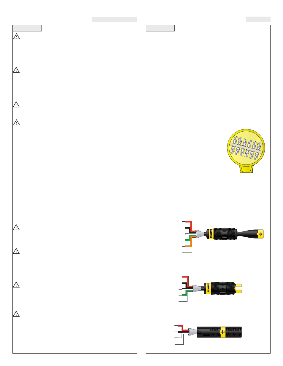
Level Switches:
Smart Trak™ will
include from 1 to 4 level switches used to
identify it’s own unique wet / dry condition.
The technologies used to indicate level are
either Ultrasonic, Buoyancy or Vibration.
Each technology features a unique
wiring/power configuration (Ultrasonic and
Vibration technologies require 12 to 36 VDC
power for operation, see below). All of the
switches are terminated in the Compact
Junction Box. The Compact Junction Box
provides a 1/2” Conduit connection and 12
poles for wire termination (for models AU45-
434_ and AZ48-434_, common terminals such as Positive (+) and
Negative (-) power must be shared).
Vibration (LZ12-1405) Wire Configuration:
RELAY
Red
Black
White
Green
Orange
(+)
(-)
NC/NO
COM
Maint.
Shld
RELAY
(+)
(-)
NO/NC
COM
Shld
Red
Black
White
Green
REED
NC
COM
NO
Shld
Red
Black
White
Ultrasonic (LU10-1305 or LU10-1325) Wire
Configuration:
Buoyancy (LV10-1301 or LV10-1351) Wire
Configuration:
Compact
Junction Box
(inside shown)