Assembly of smart trak, Assembly of switch car – Flowline AXXX Smart Trak User Manual
Page 7
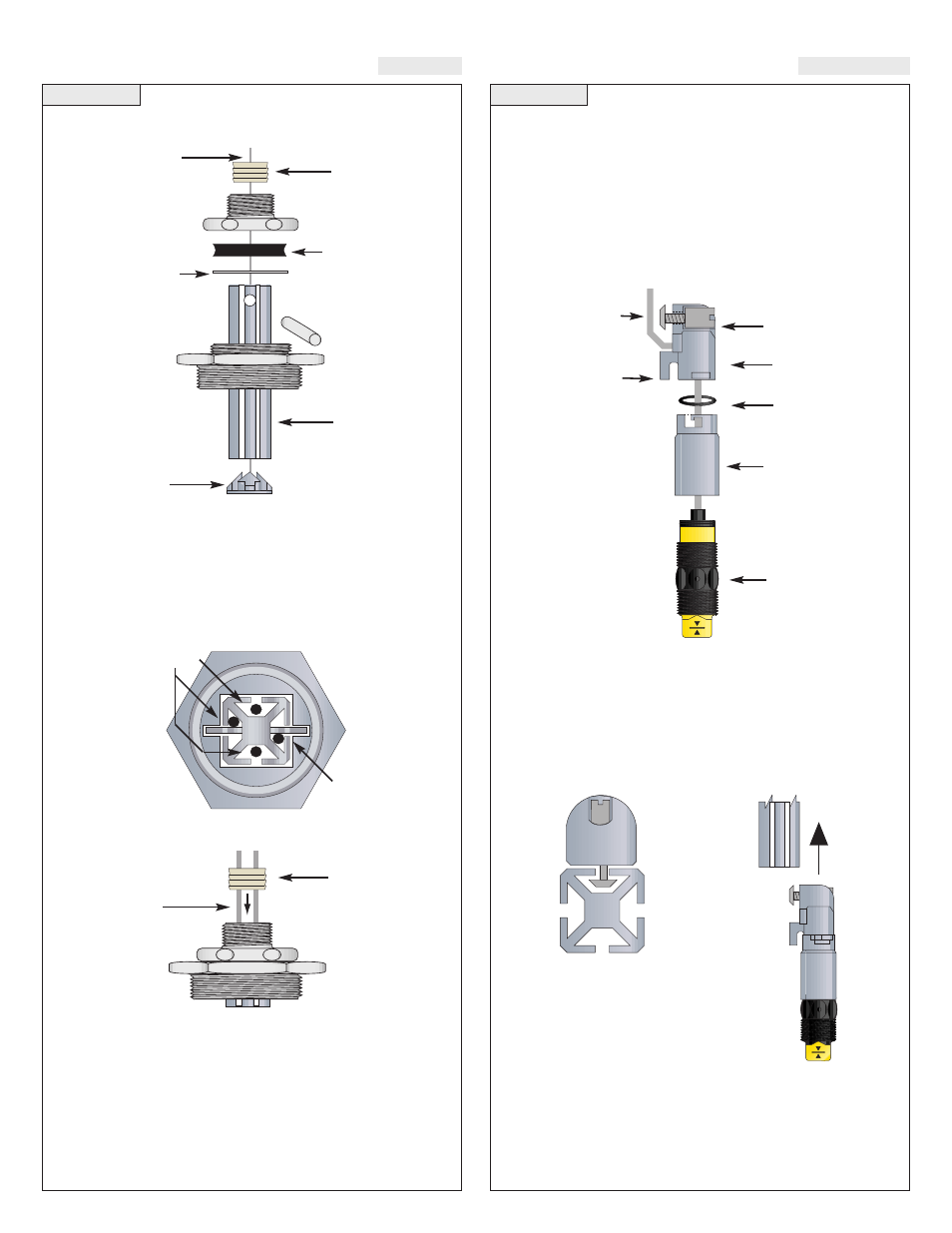
Step Nine
ASSEMBLY OF SMART TRAK™
Smart Trak™ Assembly Drawing (Side View)
Inventory:
One Smart Trak™ kit (LM10-1__1) includes the following parts:
1 Seal Plug
1 Top compression fitting
1 Wire gasket
1 Thrust Plate
1 Locking pin
1 2" NPT fitting
1 Track
1 End cap
2 Wire retainer clips (not shown)
Smart Trak™ Assembly Drawing (Top View):
Seal Plug Assembly Drawing (Side View)
Seal Plug
Seal Plug
Sensor Wire
Wire Gasket
Thrust Plate
Locking Pin
2” NPT
Fitting
2” NPT
Fitting
Cable
Cable
must fit
into side of
track next
to locking pin
Track
End cap
Wires
Top Compression
Fitting
Top Compression
Fitting
Step Ten
ASSEMBLY OF SWITCH CAR
Sensor car and bayonet adapter:
The sensor car assembly is the heart of the Smart Trak™ system. It
slides in the grooves of the track, and is locked into position by a plas-
tic bolt and screw. The bayonet to 3/4" NPT adapter has a female 3/4"
NPT fitting on one end where the sensor (not included) will screw in,
and a bayonet fitting on the other end that attaches it onto the sensor
car with a slight turn, with an O-ring in-between to provide tension
for the push-and-turn connection.
Switch Car Kit Assembly Drawing (Side View)
Inventory:
One switch car kit (LM30-10_1) consists of the following parts:
1 Locking bolt
1 Locking Nut
1 Sensor car
1 O-ring
1 Bayonet to 3/4” NPT adapter
Switch Car Kit to Smart Trak™
(Top View)
(Side View)
Determine the Proper Wire Length:
Don’t make the mistake of trimming the sensor wires too short before
the process is tested. If the sensors might need to be lowered in the
future, leave sufficient slack in the wires to allow for future adjust-
ment. This extra wire may be stored in the bottom of the terminal strip
housing, or elsewhere above the compression fitting.
Sensor
Wire
Shoe
Sensor Lock
Bolt & Nut
Sensor
Car
O-ring
Flowline
Sensor
Bayonet to
3/4” NPT
Adapter