Wiring – Flowline AXXX Smart Trak User Manual
Page 6
Step Seven
WIRING
Step Eight
WIRING
[Dry Condition]
Sensor
(NO)
RED
GRN
SHLD
WHT
BLK
LOAD
LOAD
OR
[+]
[-]
[Dry Condition]
Sensor
(NC)
BLK
GRN
SHLD
WHT
RED
LOAD
LOAD
OR
[+]
[-]
Ultrasonic and Vibration Switches
(LU10-1305, LU10-1325, LZ12-1405):
The LU10-13_5 and LZ12-1405 switch can be wired normally open
or normally closed for your application requirement. Each switch
requires 12 - 36 VDC power to operate the sensor and switch the
relay. The relay output can be wired as a dry contact. All illustrations
below identify a Dry switch state as the normal position of the relay.
Switching a Normally Open DC Load:
The Red wire connects to Positive (+) of the power supply and the
Black wire connects to Negative (-). The LOAD can be attached to
either the Green or White wires. Complete the circuit by either con-
necting the Green to (+) VDC power or White to (-) VDC power (see
illustration below).
Switching a Normally Closed DC Load:
The Black wire connects to Positive (+) of the power supply and the
Red wire connects to Negative (-). The LOAD can be attached to
either the Green or White wires. Complete the circuit by either con-
necting the Green to (+) VDC power or White to (-) VDC power (see
illustration below).
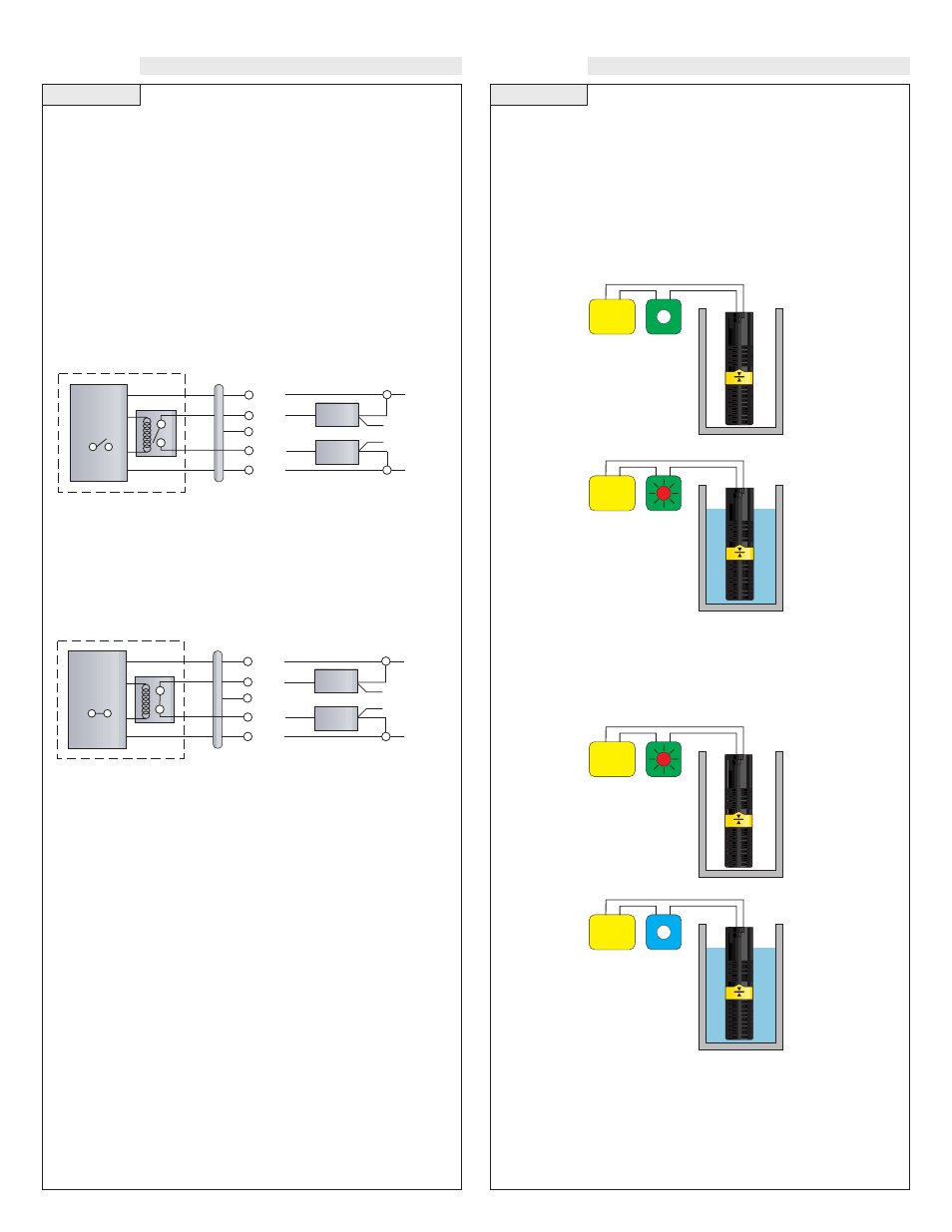
Buoyancy Level Switch (LV10-1301 & LV10-1351):
The LV10-13_1 switch can be wired normally open or normally
closed for your application requirement.
Normally Open:
Use the Black and White wires for operating the LV10-_3_1 in a nor-
mally open state. Normally open is defined as the switch being open
when the float is dry and closed when the float becomes submersed.
This operation is typical for indicating a high level.
Normally Closed:
Use the Black and Red wires for operating the LV10-_3_1 in a nor-
mally closed state. Normally closed is defined as the switch being
closed when the float is dry and open when the float becomes sub-
mersed. This operation is typical for indicating a low level.
White
Power
Supply
Black
White
Power
Supply
Black
Red
Power
Supply
Black
Red
Power
Supply
Black
Maintenance Alarm (LZ12 Vibration only):
For optimum performance and proactive maintenance, the sensor
automatically adjusts for coating, and if necessary, outputs a preven-
tative maintenance alarm. The Orange wire is a NPN transistor
designed to switch when a build-up of material prevents the vibration
switch from operating at its operational frequency. Use the Orange
wire to identify when the Vibration switch requires cleaning (see the
LZ12 manual for wiring information).