Flowline LD30 DeltaSpan User Manual
Page 4
4 of 14
MN301030
Rev B
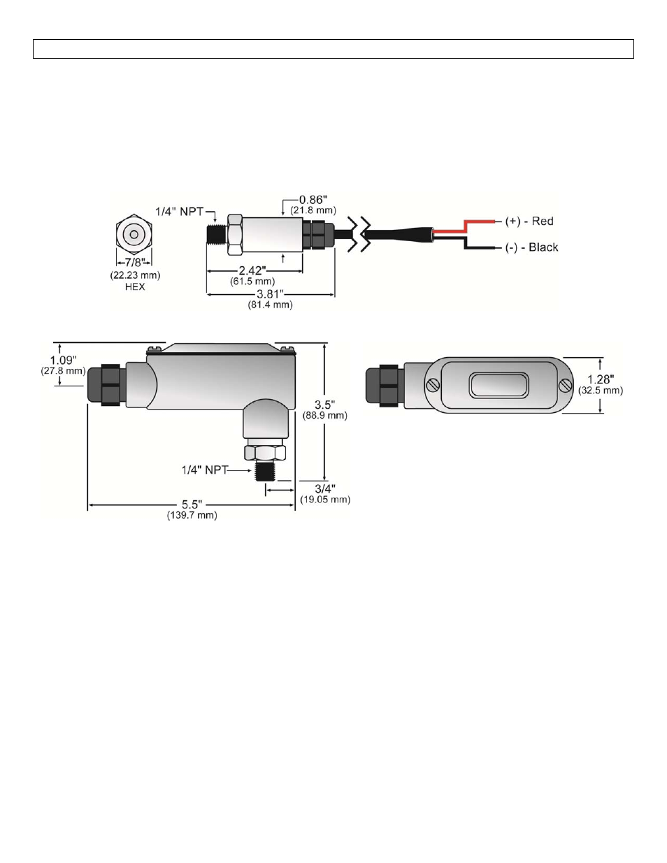
DIMENSIONS
Step Three
Technology: A pressure transmitter is installed near or on the bottom of the tank by way of a ¼” NPT thread.
A stainless steel pressure diaphragm within the pressure transmitter is exposed on one side to the application
fluid. The amount of pressure applied to the sensing surface will slightly deflect the diaphragm. The
deflection of the diaphragm is measured by a built‐in microprocessor that provides greater linearity correction
over common thermal compensation methods. A 4‐20 mA current signal proportional the height of the liquid
or the pressure of the gas is generated from the microprocessor.
Cable Series (LD30‐S_01)
Conduit Series (LD30‐S_11)
Material Compatibility:
The LD30 series is made of 316 Stainless Steel (316 SS), 316L Stainless Steel (316L SS).
The Cable Version (LD30‐S_01) is provided with 3’ (0.91 m) of cable.
The Conduit Version (LD30‐S_11) is provided with a junction box (including a terminal strip) and a ½’
NPT conduit.
The total length the signal can transmitter is based upon the following formula:
o
RLmax = (Vsup – 13V) / 0.02A,
RLmax is the total resistance including the load and the cable length.
Make sure that the switch is compatible with the application liquids. To determine the chemical compatibility
between the sensor and its application liquids, refer to the Compass Corrosion Guide, available from Compass
Publications (858‐589‐9636).