Flowline LD30 DeltaSpan User Manual
Page 11
Rev B
MN301030
11 of 14
ELECTRICAL INSTALLATION
Step Seven
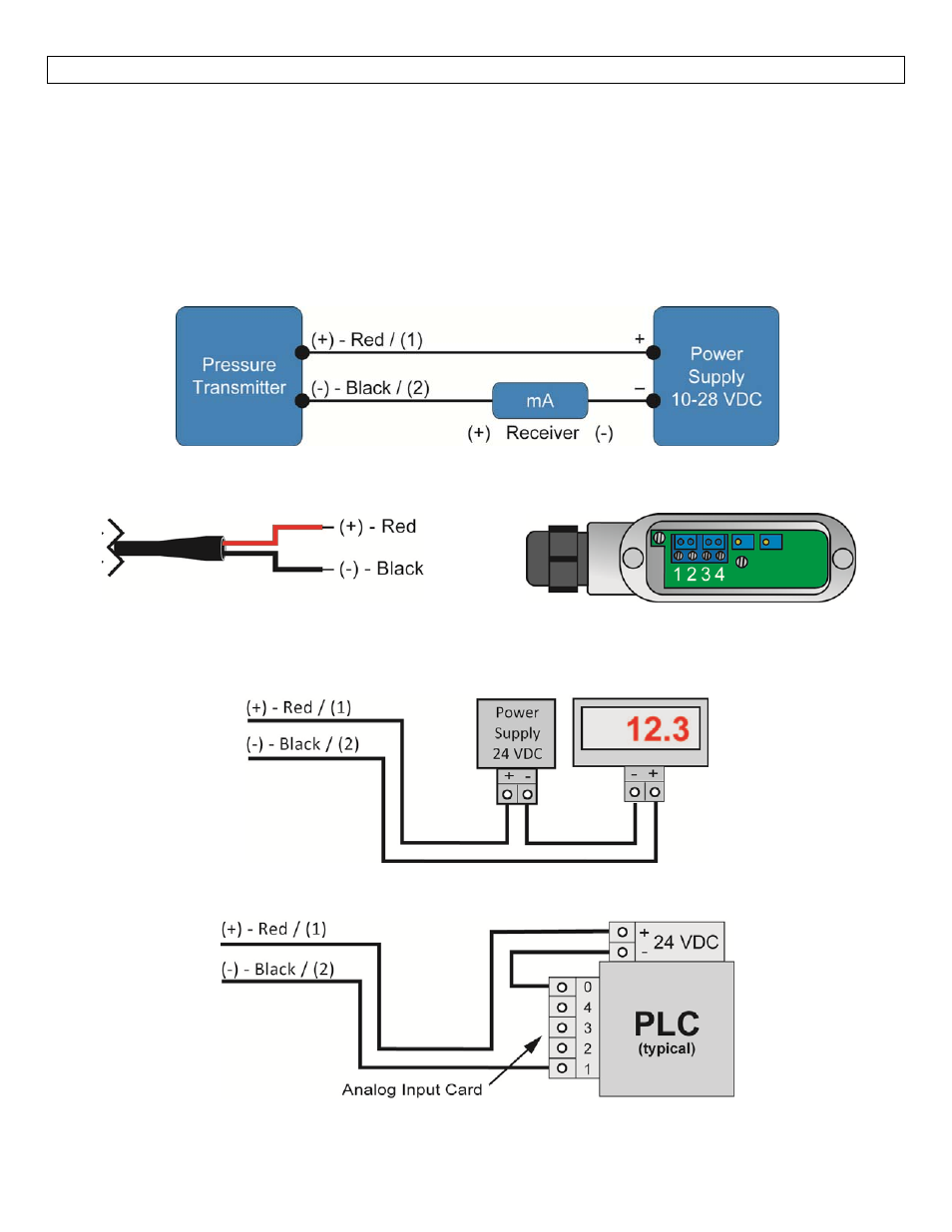
Wiring: An external power supply delivering 13‐30 VDC with minimum current capability of 40 mA DC (per
transmitter) is required to power the control loop. See Figure A below for connection of the power supply,
transmitter and receiver. The range of appropriate receiver load resistance (RL) for the DC power supply
voltage available is expressed by the formula:
RLmax = (Vsup – 10V) / 20 mA DC
Shielded cable is recommended for control loop wiring.
Use the Red wire / (1) terminal as the (+) and the Black wire / (2) terminal as the (‐).
Fig. A
Connections
Cable Version (LD30‐S_01 Series)
(+) = Red Wire & (‐) = Black Wire
Conduit Version (LD30‐S_11 Series)
(+) = Terminal #1 & (‐) = Terminal #2
Wiring to a Loop Powered Display
Wiring to a Typical PLC